Issues and Their Consequences

Production engineers used to believe that temperature was not a big issue when drilling a well and they could assume worst-case scenarios, such as constant bottomhole flowing temperature throughout the production tubing. However, deepwater drilling and high pressure/high temperature wells have had a change of perspective in engineers and the effects of trapped annular pressure and circulating temperature have become an issue for well completions.

Cathodic Protection System is a proven and reliable method of achieving corrosion control in industrial metals. Corrosion happens to be a progressively destructive process, which is initially challenging to identify until it has advanced. In most cases, corrosion is often identified when it is too late.

The effect of temperature on cementing has long been recognized and it is known that the correct determination of retarder can be critical. Usually, intermediate-string cementing is focused on achieving a great cement job and drilling ahead and not so much on issues of temperature and pressure. One of the reasons is because of the extensive use of water-based drilling fluids. Because water density is not particularly sensitive to temperature and pressure, the surface-measured mud weight does not vary much in conventional wells. However, oil-based and synthetic oil-based muds are very sensitive to temperature and pressure.

In the present, deepwater wells are encountering a lot of extreme temperature and pressure conditions. Maintaining the right pressure and predicting circulating temperature has become more critical due to weak formations and the presence of risers and choke/kill/boost lines.

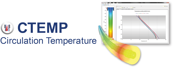
Pegasus Vertex, Inc. has created CTEMP; a technological software that predicts the well bore circulating temperature for drilling/circulating operations.

CTEMP - Circulation Temperature Software

CTEMP addresses the transient heat transfer between the wellbore and the sea water/rock formation. CTEMP’s interactive on-screen graphic results provide operation guidelines for expensive HPHT drilling operations.

For a successful wellbore stability or well control it is very important that we understand and are aware of all these issues and their consequences.

Eccentric Annulus in a Cement Job

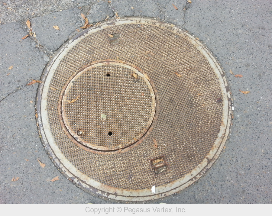
Finding a good picture of an eccentric annulus was challenging until Dennis (Global Sales Manager of PVI) and I walked down a street in downtown Calgary yesterday. I took a picture of this interesting sewerage cover. Dennis immediately guessed what I wanted to do with it, “Picture for your blog article about eccentricity?”

Eccentric Annulus

Picture 1: Eccentric Annulus

Many drilling engineering textbooks and modeling software assume concentric annulus because it is easy to model the fluid dynamics in it. Unfortunately, the most natural state of pipe in a well is almost always close to one side of the wellbore, if not touching, especially in a deviated well. Casing centralizers keep casing from contacting the wellbore wall. Even with centralizers installed, the casing between centralizers will still deform (sag) and could contact the wellbore.

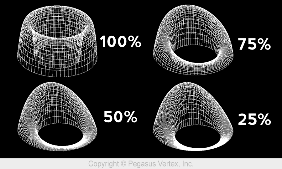
An eccentric annulus has the same cross-section area as the concentric annulus. However, the flow through the eccentric annulus exhibits various forms. The following picture shows the velocity profiles in annuli with various degrees of eccentricity. The percentage represents casing standoff. A standoff of 100% means a perfectly centered pipe while a standoff of 0% represents the situation that the casing is in contact with the wellbore.

Velocity Profiles

Picture 2: Velocity Profiles

The eccentric annulus has many unique characteristics such as less frictional pressure drop than that in concentric annulus. As the standoff gets lower, less energy is required to move the fluid, and mud removal becomes a problem in the narrow side.

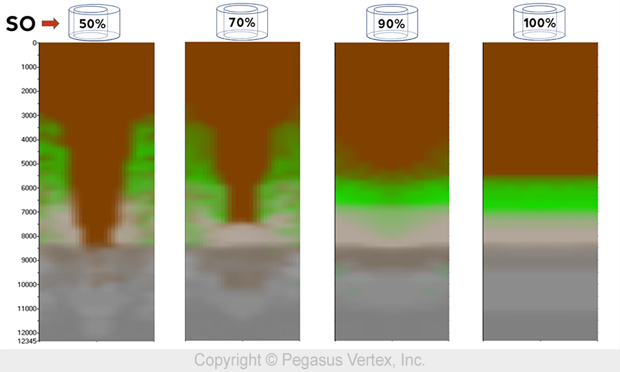
To easily view the numerically simulated results of the fluid mixture in the annulus, we are going to unwrap the annulus into a 2D picture. In this picture, the middle represents the narrow side and the 2 edges represent the wide side.

Picture 3 shows the mud concentration with various standoffs.

Mud Concentration for Various Standoff

Picture 3: Mud Concentration for Various Standoff

A well-centered pipe in a wellbore will lead to a more uniform axial velocity profile and shorter fluid interface length. As standoff approaches 0, the narrow side flow could even be blocked, leaving fluid not displaced.

From the Designing

Cementing operations represent one of the more crucial aspects regarding well integrity. Despite the vast amount of research and the large number of operations throughout the years, well integrity problems, during and after cementing jobs, is something the industry still faces. These problems have been experienced by the petroleum industry globally and can occur at any moment of the well’s life cycle. Well integrity issues have been categorized according to the moment at which they happen:

  1. During the cement displacement in the wellbore.
  2. After the cement placement.
  3. After the cement has been cured.

The first category may result in very serious well-control problems, including blowouts. During the period between 1992 and 2006, the leading cause for blowouts was cementing. These problems usually occur because of improper design of the cementing operations due to hydrostatic pressure of the cement slurries, failure when mixing the slurries to obtain the desire density, and lost circulation during the cement displacement.

The second category is normally associated with the loss of hydrostatic pressure of the cement slurries during the initial hydration period. This also can cause we-control problems, pressure build up in the annulus between the casing strings and zonal isolation problems eventually and the remedial solutions for this are normally expensive and difficult.

The last category refers to long-term problems normally caused by poor cementing jobs. Defective drilling mud removal during the cement slurry displacement in the annulus, insufficient cement height that may lead to casing leakage and corrosion problems are some of the factors that can contribute to long-term well integrity failures and the cost to fix these problems are highly expensive.

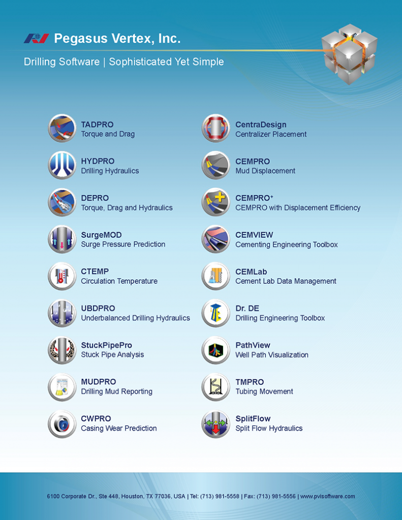
PVI has taken into consideration these types of problems and has created two great software for these situations: CEMLab and CEMPRO+.

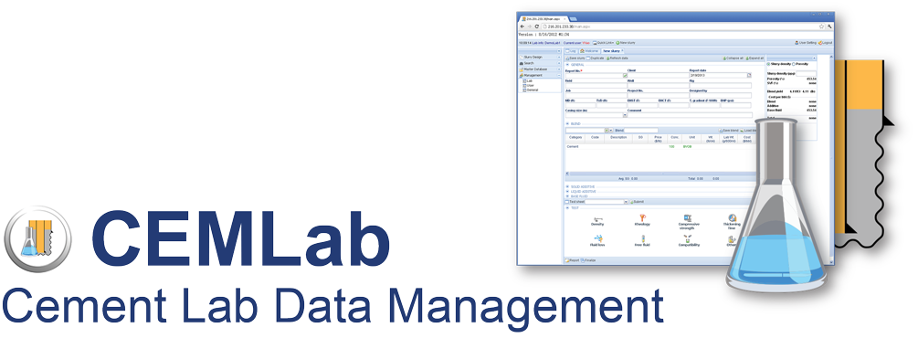
CEMLab - Cement Lab Data Management Software

CEMLab - Cement Lab Data Management Software

This integrated database management application formulates slurries and calculates lab amounts for all ingredients such as cement, dry and liquid additives, salts and water. It also generates weigh-up sheets, stores API test results and generates lab reports. CEMLab allows quick access to all slurry formulations and testing statuses from anywhere, anytime.

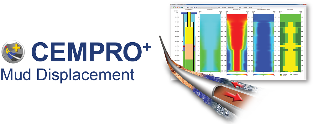
CEMPRO+ : Mud Displacement Software

CEMPRO+ : Mud Displacement Software

This mud displacement program has the capability of displacement efficiency modeling. Designed for land, offshore, conventional and/or foamed operations, CEMPRO+ accounts for many factors that can affect the efficiency of a displacement job including fluid properties, pumping rates, casing standoff and complex wellbore geometry. CEMPRO+ is the must have software for cementing operations.

Before designing your next well, keep these two models in mind to help you achieve, from the designing of the slurries to the mud displacement, a successful cementing operation.

Smart Solution

The demanding industry today continues to drill progressively challenging and costly wells, through more challenging formations.

Every year, operators lose hundreds of millions of dollars in their attempt to resolve drilling problems such as shock and vibrations, damage to bits and under-reamers, poor hole cleaning, borehole washouts, stuck pipe, plugged drillstrings and poor or inconsistent drilling performance. An analysis of worldwide drilling operation failure statistics in 2012 showed that a 38% were associated with stuck pipe, 27% caused by shock and vibration and 9% due to drillstring plugging.

Severe downhole drilling dynamics and vibration cause drillstring failures that can incur significant amounts of non-productive time. Drillers must trip out of hole either to replace bits or damaged bottom hole assemblies, perform fishing operations or drill costly sidetracks. Poor performance and reduced rates of penetration can occur when there is sufficient transfer of power to the bit, when cutting structures wear out permanently, or when rigsite personnel apply overly conservative drilling parameters due to a lack of trustworthy real time actionable information on downhole conditions.

PVI has a variety of software packages that can be an smart solution for many of these situations that operators and service companies have to deal with. For example, the software can help users to effectively reduce risks by quickly identifying the type and severity of downhole motions, detecting poor hole cleaning or sticking pipe probabilities at an early stage, plus many more. For directional drilling, users can enhance borehole quality, assist casing running and manage wellbore tortuosity. Users can also increase drilling performance by selecting drill parameters that increase the drilling efficiency and improve overall rate of penetration among many other things. For both onshore and offshore, PVI software can perform engineering calculations that optimize business and technical decisions and also provide quality engineering consulting and customized development.

Pegasus_Vertex,Inc.-Drilling_SoftwareDrilling_Software-Sophisticated_yet_Simple