Smart Solution

The demanding industry today continues to drill progressively challenging and costly wells, through more challenging formations.

Every year, operators lose hundreds of millions of dollars in their attempt to resolve drilling problems such as shock and vibrations, damage to bits and under-reamers, poor hole cleaning, borehole washouts, stuck pipe, plugged drillstrings and poor or inconsistent drilling performance. An analysis of worldwide drilling operation failure statistics in 2012 showed that a 38% were associated with stuck pipe, 27% caused by shock and vibration and 9% due to drillstring plugging.

Severe downhole drilling dynamics and vibration cause drillstring failures that can incur significant amounts of non-productive time. Drillers must trip out of hole either to replace bits or damaged bottom hole assemblies, perform fishing operations or drill costly sidetracks. Poor performance and reduced rates of penetration can occur when there is sufficient transfer of power to the bit, when cutting structures wear out permanently, or when rigsite personnel apply overly conservative drilling parameters due to a lack of trustworthy real time actionable information on downhole conditions.

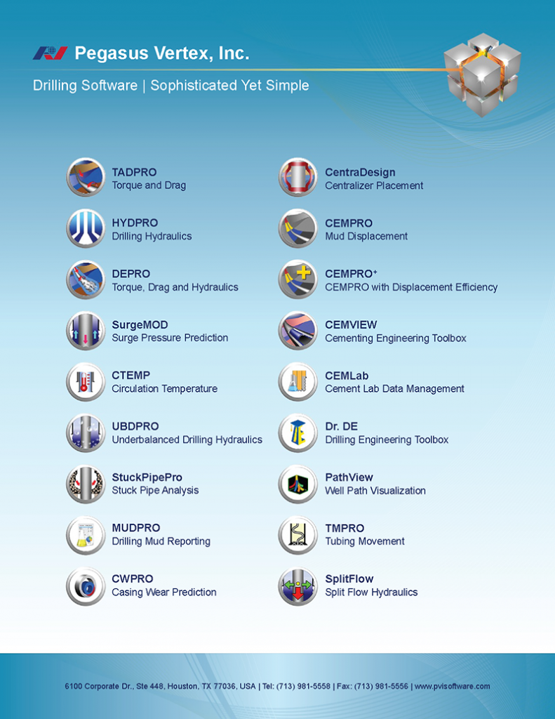
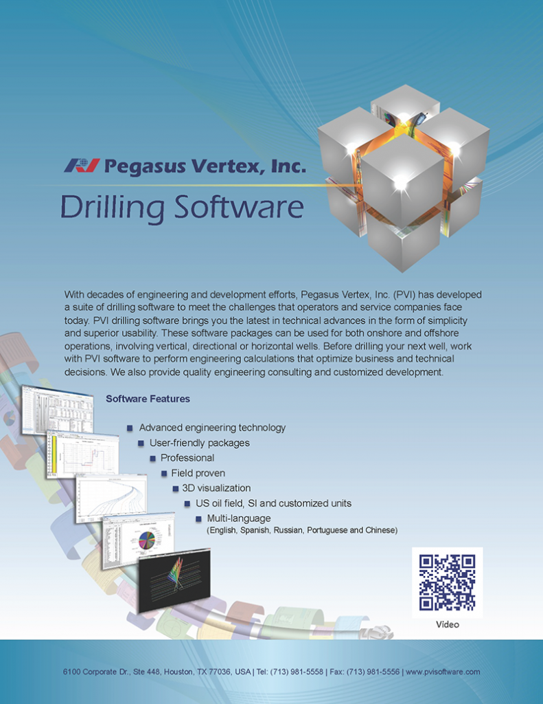
PVI has a variety of software packages that can be an smart solution for many of these situations that operators and service companies have to deal with. For example, the software can help users to effectively reduce risks by quickly identifying the type and severity of downhole motions, detecting poor hole cleaning or sticking pipe probabilities at an early stage, plus many more. For directional drilling, users can enhance borehole quality, assist casing running and manage wellbore tortuosity. Users can also increase drilling performance by selecting drill parameters that increase the drilling efficiency and improve overall rate of penetration among many other things. For both onshore and offshore, PVI software can perform engineering calculations that optimize business and technical decisions and also provide quality engineering consulting and customized development.

Pegasus_Vertex,Inc.-Drilling_SoftwareDrilling_Software-Sophisticated_yet_Simple

In Just One Click

“When I need to know the meaning of a word or a term, I look it up in a dictionary or a glossary.”

William Safire (American Journalist and presidential speechwriter)

Glossary is an alphabetical list of terms peculiar to a field of knowledge with definitions or explanations and in the oil and gas industry there’s a vast array of terminology. In an era of everything digital it is even easier to search for words or terms when not understanding clearly their meaning. Right now with just one click on Google you can get all the information you need; however, it is necessary to know exactly where to look. You can narrow down your options and are more likely to get the definition you need when you go to a specific website with its own glossary.

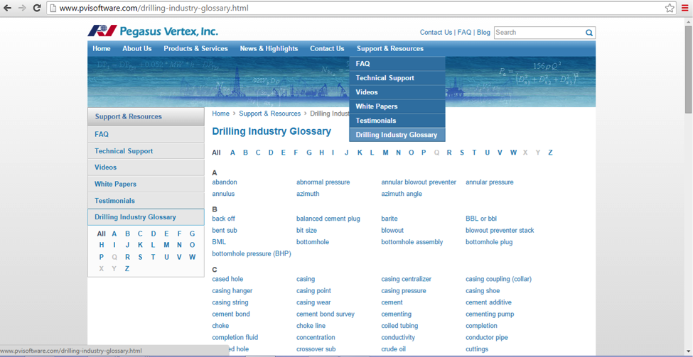
Let’s take for example our website www.pvisoftware.com. When visiting our page, go to the “Support & Resources” tab. At the bottom of the list you’ll find “Drilling Industry Glossary”.

There you will be able to search through an extensive list of drilling industry terms.

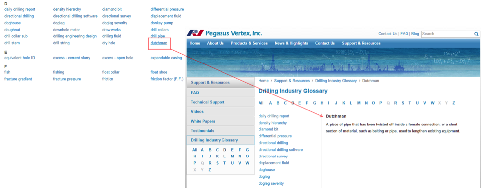
PVI Drilling_Industry_GlossaryIf you know the term you are looking for you can always go to the alphabet at the top and choose the letter the term starts with. If you don’t know the term you can scroll down and look through all the terms that are shown and click on the one you are looking for once you find it.

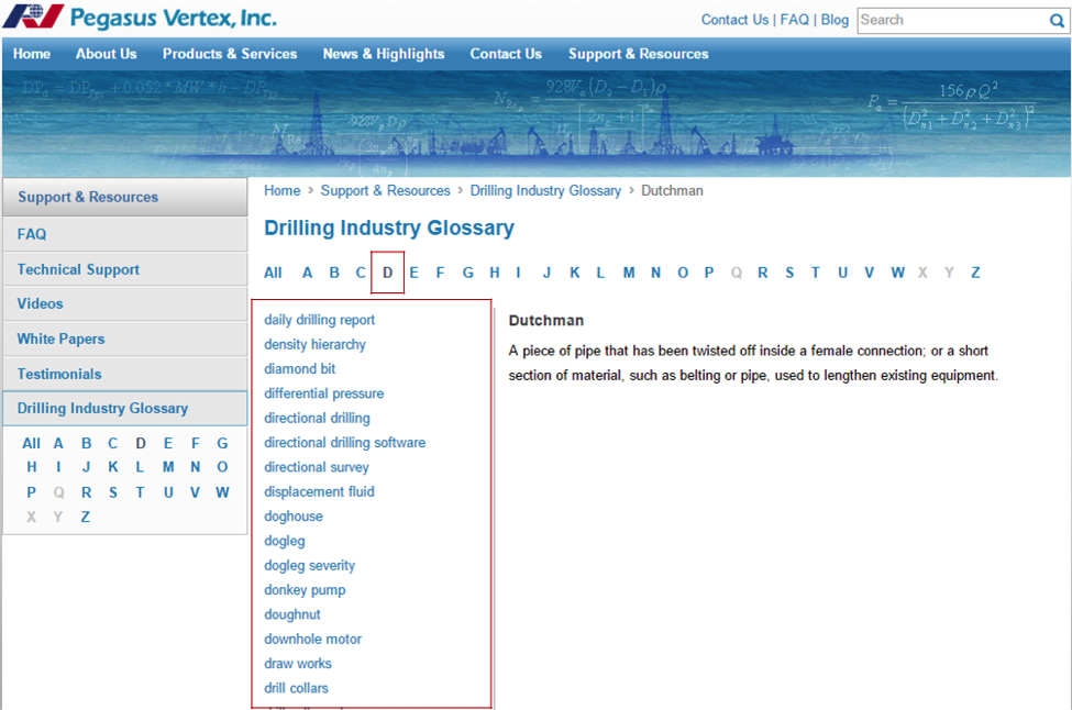
PVI Drilling_Industry_GlossaryWhen you search for a term, on the left side you will see a list of other terms that begin with the same letter as the word you were searching for.

PVI Drilling_Industry_Glossary One of the features included in this glossary is the PDF version of the entire PVI drilling industry glossary, which you can download to your own computer or print it out and have it available anytime you need it.

PVI Drilling_Industry_GlossarySince we are living in the digital era, we get to experience what it is to have access to knowledge in just one click. The opportunity is right in front of our eyes, so it’s vitally important that we seize it.

The Managing of the Mud

Drilling mud is used to assist the drilling of wellbore into the earth. Often used while drilling oil and natural gas wells and on exploration drilling rigs, mud is also used for much simpler wellbores. For instance, water wells. The three main categories of drilling fluids are water-based mud, oil-based mud, and synthetic mud. The main functions of the drilling mud include providing hydrostatic pressure to prevent formation fluids from entering into the borehole, keeping the drill bit cool and clean during drilling, carrying out drill cuttings, suspending the drill cuttings while drilling is paused, and when the drilling assembly is brought in and out of the borehole. The mud that is used for a particular job is selected to avoid formation damage and to limit corrosion.

On a drilling rig, mud is pumped from the mud pits through the drill string where it comes out of the nozzles on the drill bit, cleaning and cooling the drill bit in the process. The mud then carries the crushed or cut rock (better known as cuttings) up the annulus between the drill string and the sides of the hole

The drilling fluids carry the cuttings excavated by the drill bit up to the surface. The ability to do so depends on the cutting size, shape, density, and speed of the fluid traveling up the borehole, which is also known as annular velocity. The mud viscosity is another important property, as cuttings will settle to the bottom of the well if the viscosity is too low. Fluids that have shear thinning and elevated viscosities are efficient for wellbore cleaning. High density fluids may clean the hole adequately even with lower annular velocities, but may have a negative impact if mud weight is in excess of that needed to balance the formation pressure. For this reason, mud weight is not usually increased for hole cleaning purposes.

Mud density should be limited to the minimum necessary for well control and wellbore stability. If too great, it may fracture the formation. Depending on the mud system in use, a number of additives can improve the filter cake and therefore maintain the wellbore stability.

As we can see, mud is a vital part of drilling operations. How can mud be managed in such a way to have success in these operations? This type of mud contains carefully chosen additives to control its properties. It is the responsibility of the mud engineer to ensure that any new mud that is produced and added, meets the required specifications.

In the past, mud engineers used paper forms or Excel® spreadsheets to record mud properties, product usage, and inventory every morning. With these methods, engineers encountered problems such as disorganization of numerous daily reports and difficulty in generating end-of well recaps.

MUDPRO is a mud reporting software developed by PVI that complies with API specifications for field use.

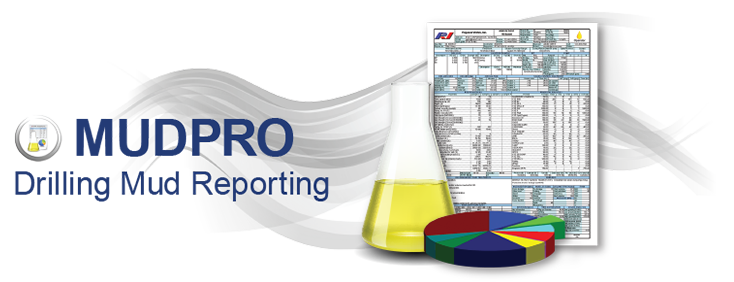
MUDPRO - Drilling Mud Reporting Software With a backbone of databases, this all-inclusive model highly improves data gathering, sharing and management. MUDPRO is designed for mud engineers at the rig sites as well as the company men in the office. A mud engineer can use it to record mud data and generate daily reports. It can also be used by company men for reviewing and managing data, making an end-of-well recap, and comparing data between multiple wells.

Step Two: Displacement

After the cement slurries have been designed and formulated the next step is:

Cementing the Well

After the casing is run into the well, a cementing head is hooked to the top of the wellhead to receive the slurries from the pumps. Then there are two wiper plugs, also known as cementing plugs (bottom plug and top plug) that sweep the inside of the casing and prevent mixing the drilling fluids with the cement slurries. The bottom plug is introduced into the well, and cement slurries are pumped into the well behind it. The bottom plug is then caught right above the bottom of the well by the float collar, which functions as a one-way valve allowing the cement slurries to enter the well. The pressure on the cement being pumped into the well increases until a diaphragm is broken within the bottom plug, permitting the slurry to flow through it and up the outside of the casing string.

Once the proper volume of cement is pumped into the wellbore, the top plug is pumped into the casing pushing the remaining slurry through the bottom plug. After the top plug reaches the bottom plug, the pumps are turned off, and the cement is allowed to set. The amount of time it takes the cement to harden is called thickening time. For setting wells at deep depths, under high temperature or pressure, as well as in corrosive environments, special cements can be employed.

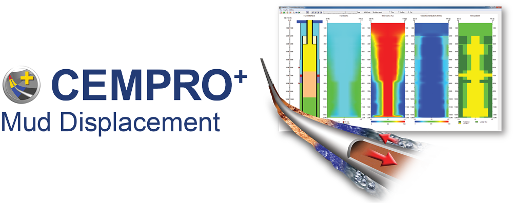
When it comes to cementing operations the ultimate and most difficult goal is to provide zonal isolation by displacing drilling mud with cement slurries because an incomplete mud removal causes a poor cement seal which can lead to a catastrophe.

PVI has developed CEMPRO+ with the capability of displacement efficiency for a successful cementing operation.

CEMPRO+ : Mud Displacement SoftwareThis software is designed for used for both land and offshore operations as well as conventional and/or foaming operations. CEMPRO+ uses advanced numerical methods to solve momentum and continuity equations on 3D grids and calculates the fluid concentration as well as the displacement efficiency. It accounts for many factors that can affect the efficiency of displacement jobs, including fluid properties, pumping rates, casing standoff, complex wellbore geometry and many more.

Step One: Preparation

Cementing a well is the procedure of developing and pumping cement into a wellbore. Although it is used for various reasons, cementing protects and seals the well. Very frequently, cementing is used to permanently block out water from penetrating the well. Cementing is also used to seal the annulus after the casing string has been run in the wellbore. In addition, cementing can be used to seal a lost circulation zone, or a specific area where there is a reduction or absence of flow inside the wellbore. When it comes to directional drilling, cementing is used to plug an existing well, in order to run a directional well from that point.

Cementing is performed when the cement slurries are placed into the well by pumps, displacing the drilling fluids that are still located in the well, and replacing them with the cement. The cement slurries flow to the bottom of the well through the casing, which will later be the pipe through which the hydrocarbons flow to the surface. From there it starts filling the space between the casing and the wellbore, and hardens. This permanently positions the casing in place and seals the wellbore so that outside materials cannot enter.

Preparing the Cement

When preparing a well for cementing, it’s very important to be certain of the amount of cement required for the job. This is done by measuring the diameter of the borehole along its depth. Also, to know the required properties of the cement is very essential before beginning any cementing operation. The proper set cement is good to be determined, including the density and viscosity of the material, before actually pumping the cement into the hole.

Special mixers are used to combine dry cement with water to create the wet cement that is also known as slurry. The cement used in the well cementing process is Portland cement, and it is calibrated with additives to form one of eight different API classes of cement. Each is employed for various situations.

Additives can include accelerators, which shorten the setting time required for the cement, as well as retarders, which do the opposite and make the cement setting time longer. In order to decrease or increase the density of the cement, lightweight and heavyweight additives are added. Additives can be added to transform the compressive strength of the cement, as well as flow properties and dehydration rates. Extenders can be used to expand the cement in an effort to reduce the cost of cementing, and antifoam additives can be added to prevent foaming inside the well. In order to plug lost circulation zones, bridging materials are also added. However, the critical part missing here is the management of numerous reports and search function.

Without an efficient lab database, we will face the following situations:

  1. Difficulty of designing cement slurries.
  2. Waste of resources to repeat similar tests.
  3. Lack of prove while job problems occur.
  4. Non-standard practices at various labs within a company.

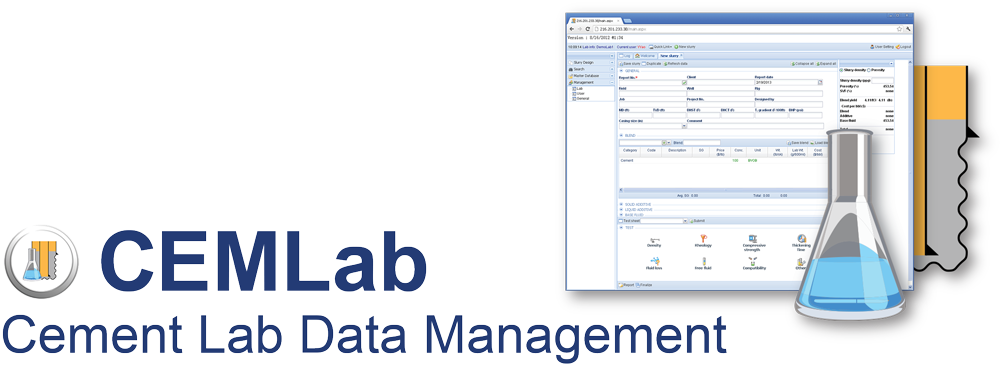
To streamline the cement lab operation, PVI developed CEMLab:CEMLab - Cement Lab Data Management SoftwareThis software is an integrated database management application that:

  • Formulates slurries.
  • Calculates lab amounts for all ingredients, such as cement, dry and liquid additives, salts and water.
  • Generates weigh-up sheets.
  • Stores API test results.
  • Generates lab reports.

CEMLab, is a web based application that allows quick access to all of your slurry formulations and testing statuses from anywhere, at any time. The advanced search function allows users to find the formula and test quickly and brings the previous jobs to their screen in no time. It’s a great tool for preparation.

Knowledge Is Power

“Knowledge is power. Information is liberating. Education is the premise of progress, in every society, in every family.”

Kofi Annan (Ghanaian diplomat)

In the petroleum industry the more knowledge we gain the more progress is made. The ability to control the downhole environment while drilling has been a dream held by drilling and reservoir engineers for decades. In the past resent years, drilling engineers focused on preventing influx of formation fluid or gas, and weighted-up their mud accordingly, but as a result, drillers found themselves indeed between the rock and a hard place.

In the early 1970s a better knowledge of drilling hydraulics started being developed. Up to this point, hydrostatic pressure and formation temperature were derived by measuring static mud weight and viscosity at the surface and calculating a pressure gradient which could be extrapolated to bit depth. Formation temperature was also calculated from a gradient. Neither parameter was precisely known. In addition, every time the mud pumps were stopped to make a connection a pressure surge was initiated when the pumps were re-started. In a formation with a tight drilling margin, this pressure spike could break down a weak spot and cause loss of circulation. Contrarily, when the drill pipe was pulled to make a bit trip or even a short trip, care had to be taken not to swab-in the well.

Drilling decisions focused on extending bit life to the maximum rather than maximizing ROP. This was accomplished by using less-aggressive bits to mitigate vibration which is the leading cause of bit wear. Float valves were installed just above the drill bit to prevent the loss of drilling fluid and to force the seawater mixture and cuttings coming down the annulus to enter the fractures. Thanks to the knowledge acquire through the years new technology has risen. Cutting-edge techniques, sustained by innovative technology, are increasing the industry's ability to safely and efficiently drill unstable formations in deepwater.

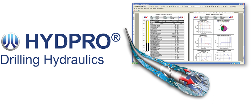
The ability to measure precisely and monitor continuously the equivalent circulating density of drilling fluid at the bit is essential for success. This is one of the functions of HYDPRO, PVI’s drilling hydraulics model.

HYDPRO - Drilling Hydraulics SoftwareThis software’s ability has allowed major strides in drilling technology that have affected safety, cost effectiveness, and efficiency. Many of the previous problems can be traced by more accurate estimations of dynamic downhole conditions.

Other functions of HYDPRO include:

  • Surge and Swab
  • Bit Optimization
  • Hole Cleaning
  • Volumetric Displacements

Like most critical undertakings, prior planning is a given. Even modular systems that are relatively easy to implement on a standard drilling unit must be carefully sized and can benefit from as much prior reservoir knowledge as possible. The benefits are important and well worth the planning effort.

Prediction Technique

Drillstring drag is the cumulative force required to move the pipe up or down inside the hole. Torque is the movement required to rotate the pipe. Drag forces usually are paralleled to the string weight measured with the string rotating but not reciprocating. Measured from the rotating string weight, the pickup drag is usually vaguely greater than the slack-off drag. The magnitudes of torque and drag are related in any particular well; high drag forces and excessive torque loads usually occur together. There are various causes for excessive torque and drag, such as tight hole conditions, keyseats, differential sticking, sloughing hole, sliding wellbore friction and cuttings buildup caused by poor hole cleaning.

With the exception of sliding friction, these causes are associated with problem conditions in the wellbore. Contrarily, in wells with great hole conditions, the primary source of torque and drag is sliding friction. Torque and drag from any source tend to be more troublesome in extended-reach directional wells. In very deep, highly deviated wells, overcoming torque and drag can be vital to the successful well completion. The capability to predict frictional loads on drillpipe has two main benefits:

  1. Deep, highly deviated wells can be planned to minimize torque and drag and ensure successful drilling operations to total depth.
  2. A more complete knowledge of drillstring loading allows use of improved drillstring design techniques, having considered the extra forces involved.

Both torque and drag are assumed to be caused entirely by sliding friction forces that result from contact of the drillstring with the wellbore. Two factors affect sliding wellbore friction:

  1. The normal contact force
  2. The coefficient of friction between the contact surfaces

The product of these two factors represents the magnitude of the sliding friction force. The normal contact force between the pipe and hole wall depends on several factors such as, the effects of gravity on the pipe, the effects of tension acting through curvatures in the wellbore and even pipe bending. The sliding friction coefficient is the ratio of the friction force to the normal contact force. This factor depends on specific contacting materials and on the degree of lubrication at various places in the wellbore. However, the oil and gas industry has made many advancements technologically speaking and quite a few models have been developed for these kind of issues.

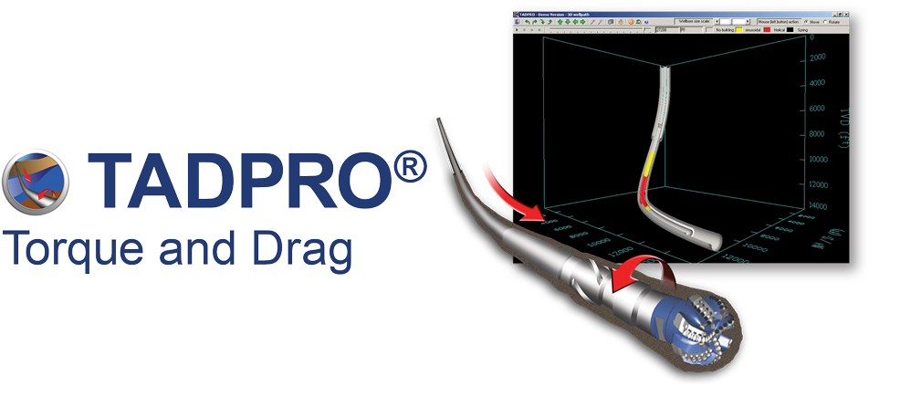
PVI’s torque and drag model, TADPRO, is designed to help remove many of the risks of a drilling program, completions design or specific tool operations. Limits in the length of a horizontal based on specific friction factors can be determined. It can evaluate the needed weight to a liner-top packer. TADPRO can analyze forces downhole and predict rig equipment specifications for torque and hookload. The model provides both versatility and accuracy in its calculations and it integrates advanced features that make it easier for our users to use.TADPRO - Torque and Drag Drilling Software

The Value of Teamwork

An organizational value is a belief that a specific mode of conduct is preferable to an opposite or contrary mode of conduct. We can think of these values as representing structures for the way we do things. Some organizations think of their values as their “guiding beacon” which directs the process of their organizational development and growth. Other companies describe them as the components of their work philosophy. Core values relate to how companies deal with their beliefs about their employees, customers and work. The studies regarding this subject show that successful companies place a great deal of emphasis on their values.

Values at work assist us by:

  • Providing a structure for how we treat one another at work.
  • Providing a structure for how we treat our customers.
  • Providing a structure for achieving the vision and increasing the effectiveness of the organization.
  • Creating an environment that leads to job satisfaction as well as finding work which is exciting and challenging.

Values at work are very important because:

  • They give us guidelines for our behavior even when we are stressed out.
  • It is a highly competitive world and they help us to show our customers how we are different from other providers.
  • People are aware of organizational values and look for them when choosing one company over another.
  • They provide the basis for achieving great change.
  • They help enable people and organizations to succeed.
  • They have an impact on professional practices.
  • They can provide a measurement of success for all employees.

WHAT OUR VALUES LOOK LIKE

Communication

Listening to and respecting each other achieves mutually beneficial results. When we are unsure we check with others as to what they meant. Everyone has strengths which we value and will use whenever possible. We request for help when needed.

Support

By providing support to one another, working co-operatively, respecting one another’s views and making our work environment fun and enjoyable, we help others to achieve their deadlines. We work with one another with enthusiasm and appreciation.

We work with one another without manipulation. Conflicts are resolved according to agreed guidelines for the team and they are brought out into the open and dealt with constructively until everyone is satisfied with the results.

Attitude

This requires being open and honest in all our dealings and maintaining the highest integrity at all times. All concerns are given with positive solutions offered. A good attitude is a skill everyone should learn to achieve.

Efficiency

Always doing what we say we will and striving for efficiency and quality in everything we do. Quality will always delight the client and keep everyone else in the company happy. We work efficiently toward a better future for the company.

Responsibility

Being responsible and committed helps the company to get successful perspectives and results both individually and collectively. Taking ownership of our customers’ needs and being accountable for delivering friendly and professional service. We are each fully accountable for our work in gaining any possible repeat business with customers.

Balance

We value learning, feedback, coaching and mentoring. Coaching and mentoring are commonplace in our company because we all coach and mentor one another. We see all opportunities as a learning experience and we pursue them. We have a balance between our personal life and our professional life and we try to keep a healthy work balance that helps us perform more efficiently. PVI Core Values

7 Basic Ideas

In completion of oil and gas wells, cement separates the wellbore, prevents casing failure, and keeps wellbore fluids from contaminating freshwaters. The basic factors engineers and operators must consider for successful cementing jobs are summarized in seven basic ideas:

  1. Condition the Drilling Fluid
  2. Use Centralizers
  3. Move the Pipe
  4. Increase the Displacement Rate
  5. Design Slurries for Proper Temperature
  6. Select and Test Cement Components
  7. Select a Proper Cementing System

1. Condition the Drilling Fluid

The drilling fluid condition is the most important variable in achieving very good displacement during a cementing job. As the workers pull the drill pipe, run the casing, and prepare for cementing operations, the drilling fluid in the wellbore basically remains static and hardens. Pockets of mud commonly exist after a wellbore is drilled and they make displacement difficult. These pockets of gelled fluid must be broken up. Regaining and maintaining good fluid mobility after running the casing is essential.

2. Use Centralizers

Centralizers are effective mud displacement helpers. Centralizers make easier the removal of gelled-mud and allow better cement bond with the wellbore. Centralizers are designed to serve various needs, for instance, they help with well control, provide increased mud-removal benefits, optimize drilling-fluid displacement. When a casing is poorly centralized the cement bypasses drilling fluid by following the path of least resistance. Good pipe standoff helps ensure uniform flow patterns around the casing. Centralizers also change fluid flow patterns and promote better mud displacement and removal.

3. Move the Pipe

Moving the casing before and during cementing breaks up the gelled pockets and it loosens the cuttings trapped in the gelled mud. Pipe movement allows high displacement efficiency at lower pump rates by keeping the drilling fluid flowing.

Movement compensates partially for poorly centralized casing by changing the flow path and allowing the slurries to circulate completely around the pipe. In some instances, some liner hangers and mechanical devices prevent casing movement, which must be considered during the cement displacement design.

4. Increase the Displacement Rate

High-energy flow in the annulus is more effective in ensuring good mud displacement. Turbulent flow around the casing circumference is desirable, but not necessarily essential. The best cementing results are obtained when the spacers and cement are pumped at maximum energy, the spacer is appropriately designed to remove the mud, and a more proficient cement is used.

5. Design Slurries for Proper temperature

Operators can optimize the slurry design if they know the actual temperature the cement will encounter. Bottomhole cementing temperatures affect the slurry thickening time, set time, rheology and the compressive-strength development. Operators tend to overestimate the amount of materials required to keep cement in a flowing for pumping, which can result in unnecessary cost and well-control problems. They can optimize cost and displacement efficiency by designing the job on the basis of actual wellbore circulating temperatures, obtained from a downhole temperature sub recorder.

6. Select and Test Cement components

Operators are encouraged to design cement slurries for specific applications, with good properties to allow placement in a normal period of time. The ideal cement slurries have no measurable free water, provide adequate fluid-loss control, have adequate retarder to ensure proper placement, and maintain a stable density to ensure hydrostatic control.

Before performing the job, they should check the cement reaction and actual location mix water to ensure that the formulation will perform as it is expected. Contaminants in the mix water can produce large variances in thickening time and compressive strength.

Organic materials and dissolved salts in mix water can affect the slurries setting time.

Cement dehydration from the loss of filtrate to permeable formations can cause bridging and increased friction pressure, viscosity, and density. Pump pressures can increase and additives can be used to provide fluid-loss control when is necessary to compensate for dehydration.

7. Select a Proper Cementing System

Operators select cement systems based on job objectives and well requirements.

Cement is basically inflexible. Cementing systems are similar in many ways, but sometimes they vary, for instance, in their capability to provide good zone isolation in changing environments. The cement selection has always been on the basis that higher compressive strengths result in higher cement sheath quality. Research has proven that the ability of cement to provide good zonal isolation is better defined by other mechanical properties. Good isolation does not necessarily require high compressive strength. The real competence test is whether the cement system in place can provide zone isolation for the life of the well.

For all these situations PVI has developed a series of software such as:

CentraDesign - Centralizer Placement Software
CentraDesign - Centralizer Placement Software

MUDPRO - Drilling Mud Reporting Software

MUDPRO - Drilling Mud Reporting Software

StuckPipePro - Stuck Pipe Analysis Software

StuckPipePro - Stuck Pipe Analysis Software

that can help engineers and operators to perform a better quality job and avoid any potential problems that can put at risk the production.

A New Drilling Engineering Toolbox App

Every drilling engineer and technician knows that performing drilling engineering calculations can be a tedious and time-consuming process, considering the many researches they have to do in order to find the right results. At times, even these results are not quite exact. While technology has tremendously driven the oil and gas industry forward with the creation and development of advanced software, most of the time these are meant to be used in the office and are not so simple and portable. To assist with this issue, Pegasus Vertex, Inc. has launched the new DR.DE Lite mobile app for both Android and Apple devices. This free app was developed to provide drilling engineers and technicians with a simple, useful, paperless and portable tool to make their drilling engineering calculations easier and faster.

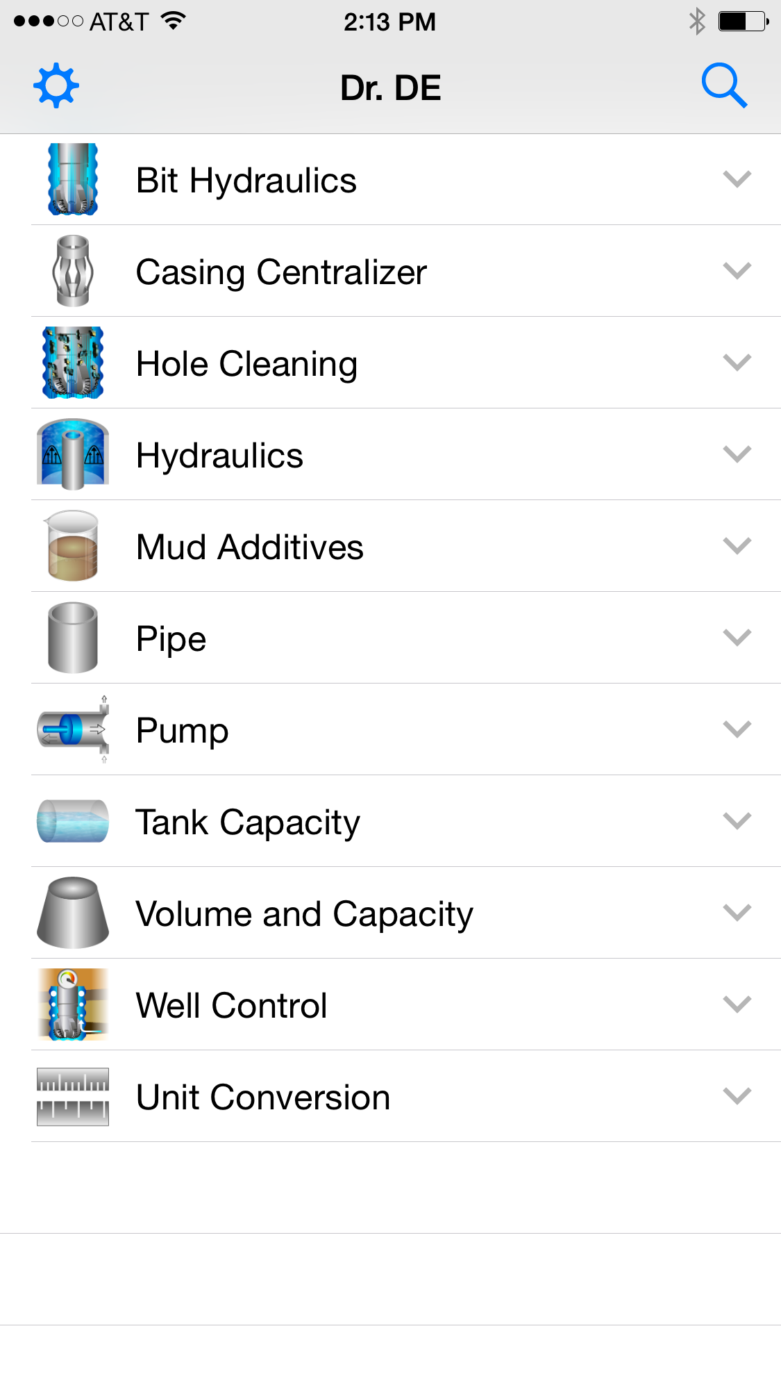
Dr.DE_Lite_Mobile_AppThe DR.DE Lite app is equipped with 29 functions that are divided into 11 groups.

Dr.DE Lite App: 11 GroupsFrom this great selection of functions, this tool can help you save time and efforts to get the calculations you need. In the past, drilling engineers and technicians had to obtain the information from different sources and after gathering the information manually perform the calculations and that could take up to an hour; however, now it can be done in a matter of seconds and the results are precise.

In this new tool, every function comes with three main buttons: Default, Clear and Calculate. The “Default” button gives users an example of standard input data. The “Clear” button allows users to delete all input data and the “Calculate” button performs the calculations based on the data users enter. The app collects all the information the users provide and in case the wrong data is entered, it will give a message as a warning.

For example, the “Hydraulic’ group contains four sub-functions: 1. ECD, which calculates the ECD at depth. 2. Hydrostatic pressure, which calculates the hydrostatic pressure of the mud column in a deviated well. 3. Pressure drop (Bingham) annulus, which calculates the pressure drop in an annular section for Bingham plastic fluids. 4. Pressure drop (Power law) annulus, which calculates the pressure drop in an annular section for power-law fluids.

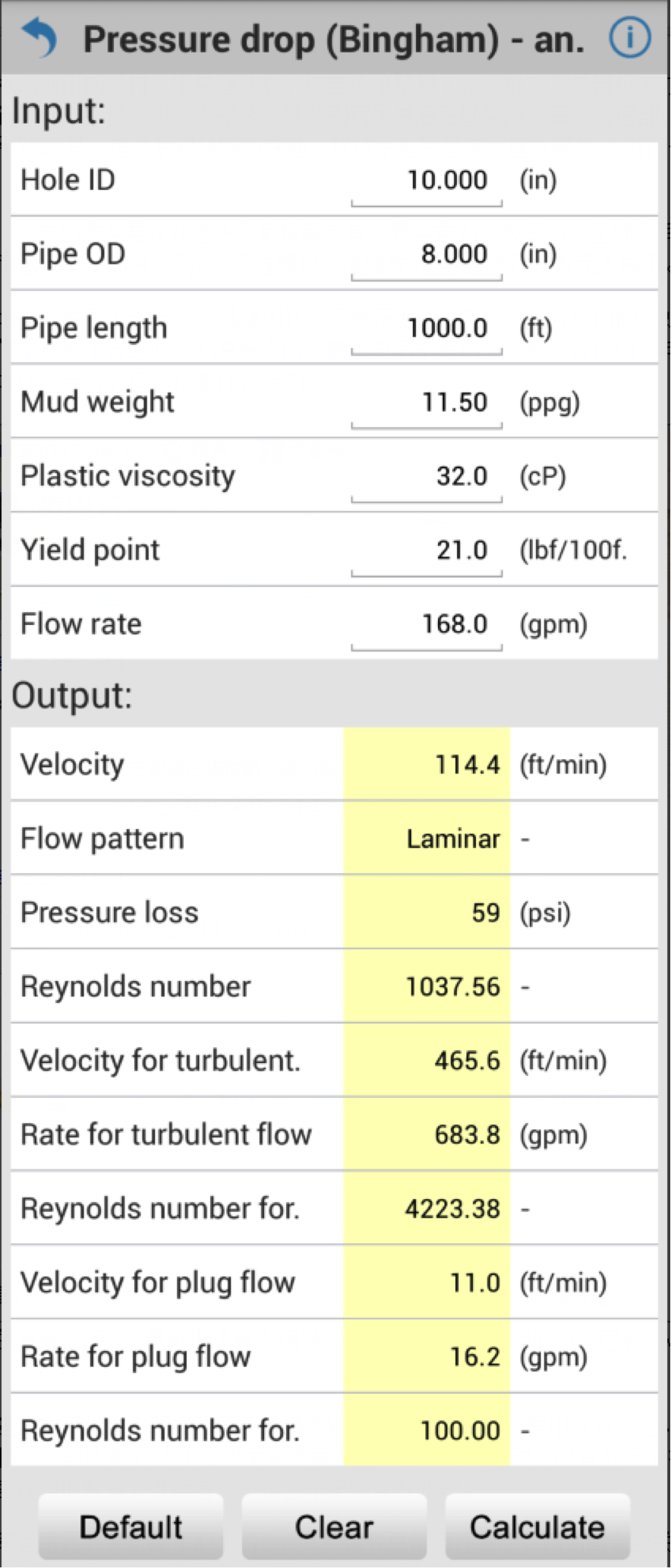
Dr.DE Lite: Pressure DropIn the “Pressure drop” function, users can specify the wellbore configuration, as well as fluid properties and flow rates. DR.DE Lite performs calculations for fluid velocity, flow pattern, pressure drop, Reynolds number and other key parameters for different flow patterns.

The DR.DE Lite app is the perfect tool that complements your work. It’s easy to download, easy to use, very convenient and free. To download DR.DE Lite, scan the QR code or download the app from your mobile play store.

Dr.DE_Lite: Free Drilling Engineering Toolbox Mobile App