Step Two: Displacement

After the cement slurries have been designed and formulated the next step is:

Cementing the Well

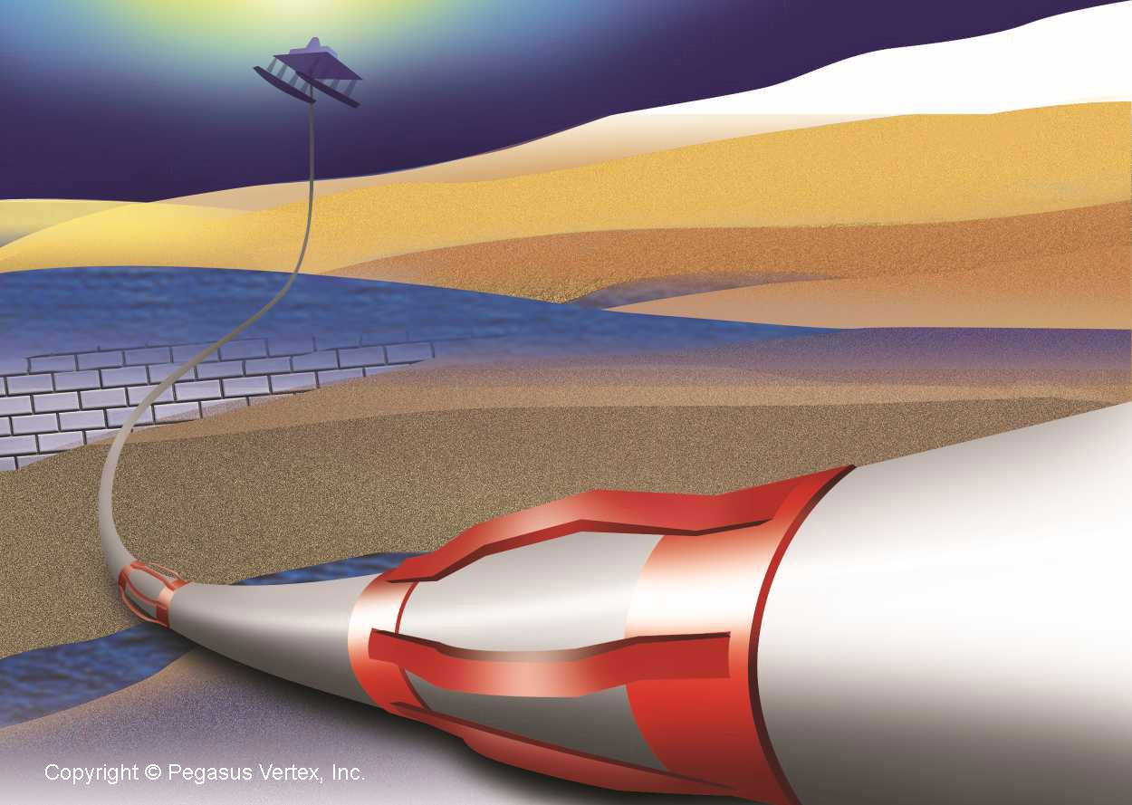
After the casing is run into the well, a cementing head is hooked to the top of the wellhead to receive the slurries from the pumps. Then there are two wiper plugs, also known as cementing plugs (bottom plug and top plug) that sweep the inside of the casing and prevent mixing the drilling fluids with the cement slurries. The bottom plug is introduced into the well, and cement slurries are pumped into the well behind it. The bottom plug is then caught right above the bottom of the well by the float collar, which functions as a one-way valve allowing the cement slurries to enter the well. The pressure on the cement being pumped into the well increases until a diaphragm is broken within the bottom plug, permitting the slurry to flow through it and up the outside of the casing string.

Once the proper volume of cement is pumped into the wellbore, the top plug is pumped into the casing pushing the remaining slurry through the bottom plug. After the top plug reaches the bottom plug, the pumps are turned off, and the cement is allowed to set. The amount of time it takes the cement to harden is called thickening time. For setting wells at deep depths, under high temperature or pressure, as well as in corrosive environments, special cements can be employed.

When it comes to cementing operations the ultimate and most difficult goal is to provide zonal isolation by displacing drilling mud with cement slurries because an incomplete mud removal causes a poor cement seal which can lead to a catastrophe.

PVI has developed CEMPRO+ with the capability of displacement efficiency for a successful cementing operation.

CEMPRO+ : Mud Displacement SoftwareThis software is designed for used for both land and offshore operations as well as conventional and/or foaming operations. CEMPRO+ uses advanced numerical methods to solve momentum and continuity equations on 3D grids and calculates the fluid concentration as well as the displacement efficiency. It accounts for many factors that can affect the efficiency of displacement jobs, including fluid properties, pumping rates, casing standoff, complex wellbore geometry and many more.

7 Basic Ideas

In completion of oil and gas wells, cement separates the wellbore, prevents casing failure, and keeps wellbore fluids from contaminating freshwaters. The basic factors engineers and operators must consider for successful cementing jobs are summarized in seven basic ideas:

  1. Condition the Drilling Fluid
  2. Use Centralizers
  3. Move the Pipe
  4. Increase the Displacement Rate
  5. Design Slurries for Proper Temperature
  6. Select and Test Cement Components
  7. Select a Proper Cementing System

1. Condition the Drilling Fluid

The drilling fluid condition is the most important variable in achieving very good displacement during a cementing job. As the workers pull the drill pipe, run the casing, and prepare for cementing operations, the drilling fluid in the wellbore basically remains static and hardens. Pockets of mud commonly exist after a wellbore is drilled and they make displacement difficult. These pockets of gelled fluid must be broken up. Regaining and maintaining good fluid mobility after running the casing is essential.

2. Use Centralizers

Centralizers are effective mud displacement helpers. Centralizers make easier the removal of gelled-mud and allow better cement bond with the wellbore. Centralizers are designed to serve various needs, for instance, they help with well control, provide increased mud-removal benefits, optimize drilling-fluid displacement. When a casing is poorly centralized the cement bypasses drilling fluid by following the path of least resistance. Good pipe standoff helps ensure uniform flow patterns around the casing. Centralizers also change fluid flow patterns and promote better mud displacement and removal.

3. Move the Pipe

Moving the casing before and during cementing breaks up the gelled pockets and it loosens the cuttings trapped in the gelled mud. Pipe movement allows high displacement efficiency at lower pump rates by keeping the drilling fluid flowing.

Movement compensates partially for poorly centralized casing by changing the flow path and allowing the slurries to circulate completely around the pipe. In some instances, some liner hangers and mechanical devices prevent casing movement, which must be considered during the cement displacement design.

4. Increase the Displacement Rate

High-energy flow in the annulus is more effective in ensuring good mud displacement. Turbulent flow around the casing circumference is desirable, but not necessarily essential. The best cementing results are obtained when the spacers and cement are pumped at maximum energy, the spacer is appropriately designed to remove the mud, and a more proficient cement is used.

5. Design Slurries for Proper temperature

Operators can optimize the slurry design if they know the actual temperature the cement will encounter. Bottomhole cementing temperatures affect the slurry thickening time, set time, rheology and the compressive-strength development. Operators tend to overestimate the amount of materials required to keep cement in a flowing for pumping, which can result in unnecessary cost and well-control problems. They can optimize cost and displacement efficiency by designing the job on the basis of actual wellbore circulating temperatures, obtained from a downhole temperature sub recorder.

6. Select and Test Cement components

Operators are encouraged to design cement slurries for specific applications, with good properties to allow placement in a normal period of time. The ideal cement slurries have no measurable free water, provide adequate fluid-loss control, have adequate retarder to ensure proper placement, and maintain a stable density to ensure hydrostatic control.

Before performing the job, they should check the cement reaction and actual location mix water to ensure that the formulation will perform as it is expected. Contaminants in the mix water can produce large variances in thickening time and compressive strength.

Organic materials and dissolved salts in mix water can affect the slurries setting time.

Cement dehydration from the loss of filtrate to permeable formations can cause bridging and increased friction pressure, viscosity, and density. Pump pressures can increase and additives can be used to provide fluid-loss control when is necessary to compensate for dehydration.

7. Select a Proper Cementing System

Operators select cement systems based on job objectives and well requirements.

Cement is basically inflexible. Cementing systems are similar in many ways, but sometimes they vary, for instance, in their capability to provide good zone isolation in changing environments. The cement selection has always been on the basis that higher compressive strengths result in higher cement sheath quality. Research has proven that the ability of cement to provide good zonal isolation is better defined by other mechanical properties. Good isolation does not necessarily require high compressive strength. The real competence test is whether the cement system in place can provide zone isolation for the life of the well.

For all these situations PVI has developed a series of software such as:

CentraDesign - Centralizer Placement Software

CentraDesign - Centralizer Placement Software

MUDPRO - Drilling Mud Reporting Software

MUDPRO - Drilling Mud Reporting Software

StuckPipePro - Stuck Pipe Analysis Software

StuckPipePro - Stuck Pipe Analysis Software

that can help engineers and operators to perform a better quality job and avoid any potential problems that can put at risk the production.
Buried Jewelry: Casing Centralizers

People in ancient time had different burial customs that they believed were necessary to ensure their immortality after death. For example, the ancient Egyptians followed some rituals and protocols which included mummification, casting of magic spells and burial with specific grave goods thought to be needed in the Egyptian afterlife.

The ancient Chinese believed that the afterlife was a continuation of life on earth. Therefore, it was very important that all things they needed were buried with them in their tomb, including their jewelry.

Incidentally, in the oil well cementing business, people sometimes refer to the centralizers as “the cementing jewelry”, probably because they are installed on a casing string in a way similar to a bracelet on the wrist.

Centralizer On Casing

Centralizer On Casing

Casing centralizer is a mechanical device secured around the casing at various locations to keep the casing from making contact with the wall. As a result of casing centralization, a continuous annular clearance around the casing allows cement to completely seal around the casing to the borehole wall.

Because of the cementation of casing with centralizers underground, casing centralizers are literally buried jewelry.

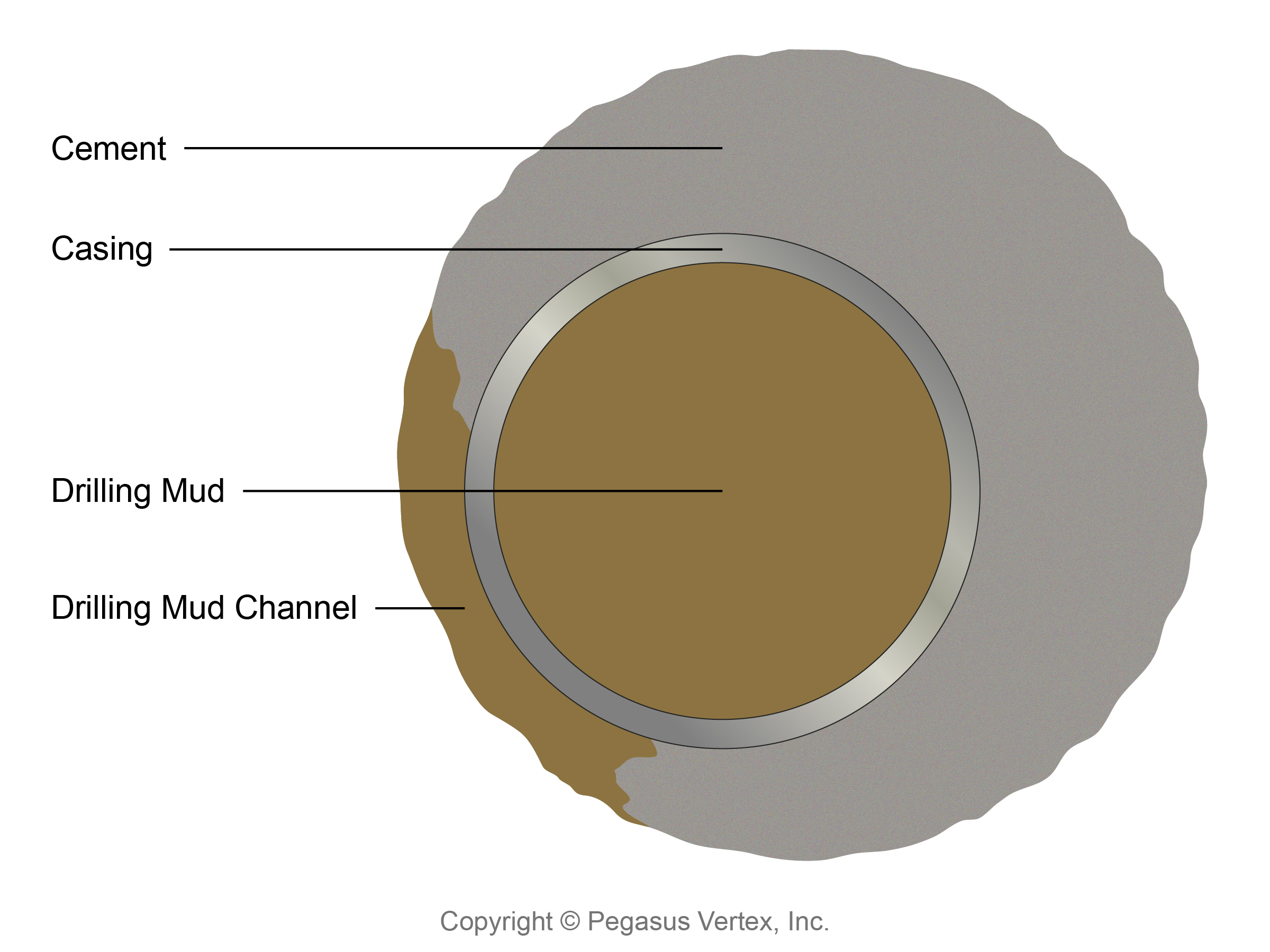
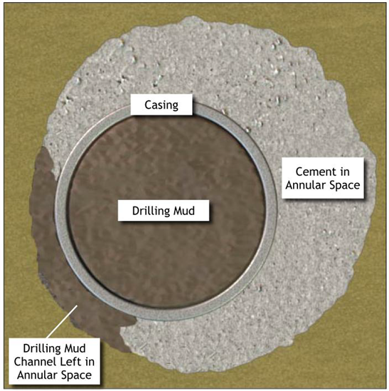
Unlike those real jewelry buried in tombs, these centralizers provide a vital function in zonal isolation. Without centralizers, the casing touches the wellbore. In this case, cement slurry will have difficulty displacing mud in the narrow side of an eccentric annulus during a cementing job. This will lead to incomplete displacement of mud or mud channel as shown in the following picture.

Mud ChannelMud channel weakens the cement bond between the casing and the formation. The good news is that with a computer software like CentraDesign, it is easier than ever to choose the right centralizer type with certain properties and place them strategically along the casing for a particular well path.

Each well is different and centralizer types and properties vary. It is best to perform a standoff analysis for each casing before a cementing job. Note that the total number of centralizers required and their placement on the casing are equally important.

Floating Egg

I did a simple science project with my 8-year-old daughter to show the action of buoyancy.

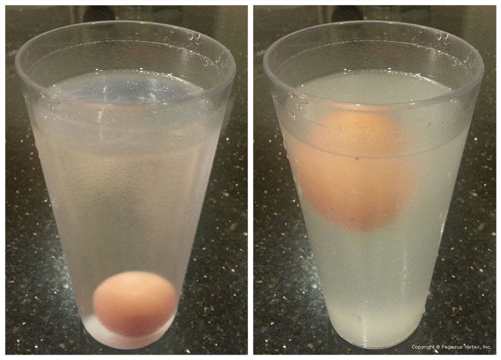
Step 1: Put a raw egg in a glass full of water. The egg sinks to the bottom.

Step 2: Keep adding salt and stir the water.  You will feel guilty of wasting too much salt, but eventually, the egg arises.

Before / After Adding Salt

My daughter and I were both amazed by this simple demonstration of buoyancy of salt water. Recall that Archimedes’ principle states that the upward force on a submerged object (egg) is equal to the weight of the water that it displaces. Salt water weights more than fresh water, this difference of upward force (buoyancy) makes the egg arise.

In drilling mud situations, saltwater drilling fluids can be formulated with high-density brines, such as calcium chloride, calcium bromide, etc. The mud weight is dependent upon the specific gravity (SG) of salts added and concentration of these salts. The heavier the mud, the higher the bottom hole pressure is. Note that one of the main functions of drilling fluids is to provide hydrostatic pressure to prevent formation fluids from entering into the well. Heavy mud brings some advantages and some disadvantages to other aspects of drilling operations because of the buoyancy it creates.

Buoyancy makes drill string appear light. This reduces the side force, which pushes drill string against wellbore. Therefore, there is less torque and drag for a heavier drilling fluid system, but what helps also causes problems in this case: too much buoyancy revokes the effectiveness of transferring the pipe weight to the bit.

When cementing a casing, due to the large size of the casing and the big difference of fluid densities in the annulus and inside the pipe, the buoyancy could be so great that the casing could be pushed out of the hole if it is not chained down.

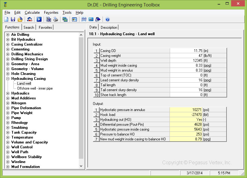
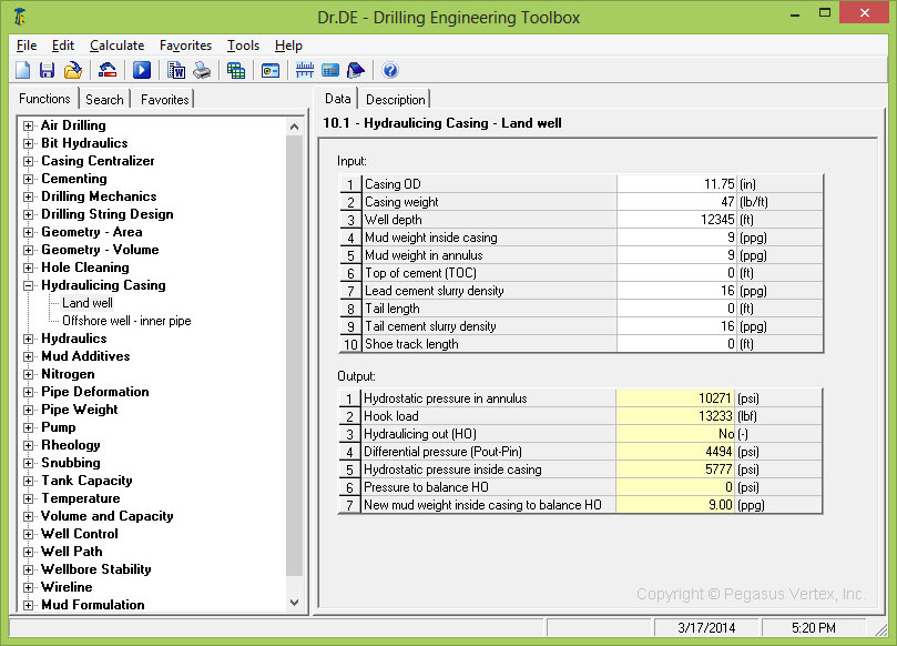
Let’s use Dr.DE (drilling engineering tool box software) to show a couple of examples.

Consider an 11.75” OD casing with weight of 47lb/ft. The casing shoe is at 12,345 ft in a vertical well. The annulus is full of cement slurry of 16ppg. We assume mud weight of 8.33 ppg. With the help of Dr.DE the calculation shows that the casing will be lifted up.

Casing will be lifited up | Dr.DE - drilling toolbox

Casing Will Be Lifited Up

Now, change the mud weight to 9 ppg, due to this change, the hydraulic pressure inside the casing increases and the casing will not be lifted up by the buoyancy.

Casing will NOT be lifited up | Dr. DE Drilling Toolbox

Casing will NOT be lifited up

The Best is Yet to Come

The following is told by an American lady:

“My grandmother always used to tell us, “keep your forks.” when the main dishes were being cleared from the table. It was my favorite part of dinner, because I knew that something wonderful was coming… like a velvety chocolate cake or a deep-dish apple pie.”

A similar expression would be “You have not seen anything yet.” or as my 8-year old daughter told me, “I am not done yet!” when I gave her an applause after she sang the song from the movie “Frozen”.

Life is a simple and normal routine. Everyone has the same number of hours in a day and the same number of days in a year. It is up to us to make our daily routines more interesting, to fill our time doing things that will make us grow in every aspect of our lives, to make the most of our time. We cherish the hope that our present situation is not our final destination. The best is yet to come.

For us software developers, we are continuously enhancing the drilling software that is being developed. We certainly can’t add more hours to our day, but we can make our development more efficient. We will probably spend the same amount of time as we did last year, but we will have better products in 2014.

The latest release of our cementing software CEMPRO+ is a milestone. Why? Because this is the first time we address the displacement efficiency during the multi-fluid displacement operations such as cementing or wellbore cleanup. Before CEMPRO+ we used to assume that the drilling mud was completely displaced by the cement slurry with the use of a piston. This convenient assumption makes the hydraulics relatively easy, but it fails to predict the mud channeling which occurs due to many factors such as, differences in the cement properties and mud flow rates, and the casing centralization. A typical illustration of mud channeling is shown here:

Mud channel left on the narrow side of the annulus

Mud channel left on the narrow side of the annulus (Macondo incident-Chief Counsel’s report, 2011)

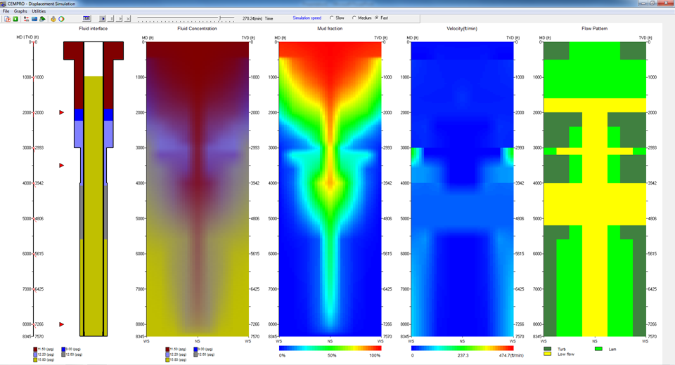
CEMPRO+ can help predict the mud fractions in the annulus during a cementing job. The following picture is a snap shot from the program. It looks neat. Graphics are more significant, because they show what really happens in the wide and narrow sides of the annulus.

Displacement Efficiency Illustration in CEMPRO+

Displacement Efficiency Illustration in CEMPRO+

If our CEMPRO has been on your software menu, keep your forks, because the best is yet to come.