Step Two: Displacement

After the cement slurries have been designed and formulated the next step is:

Cementing the Well

After the casing is run into the well, a cementing head is hooked to the top of the wellhead to receive the slurries from the pumps. Then there are two wiper plugs, also known as cementing plugs (bottom plug and top plug) that sweep the inside of the casing and prevent mixing the drilling fluids with the cement slurries. The bottom plug is introduced into the well, and cement slurries are pumped into the well behind it. The bottom plug is then caught right above the bottom of the well by the float collar, which functions as a one-way valve allowing the cement slurries to enter the well. The pressure on the cement being pumped into the well increases until a diaphragm is broken within the bottom plug, permitting the slurry to flow through it and up the outside of the casing string.

Once the proper volume of cement is pumped into the wellbore, the top plug is pumped into the casing pushing the remaining slurry through the bottom plug. After the top plug reaches the bottom plug, the pumps are turned off, and the cement is allowed to set. The amount of time it takes the cement to harden is called thickening time. For setting wells at deep depths, under high temperature or pressure, as well as in corrosive environments, special cements can be employed.

When it comes to cementing operations the ultimate and most difficult goal is to provide zonal isolation by displacing drilling mud with cement slurries because an incomplete mud removal causes a poor cement seal which can lead to a catastrophe.

PVI has developed CEMPRO+ with the capability of displacement efficiency for a successful cementing operation.
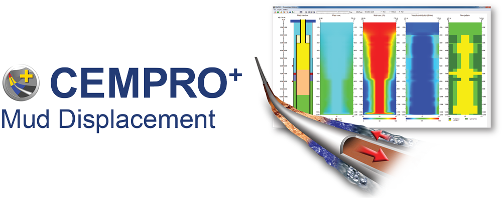
CEMPRO+ : Mud Displacement SoftwareThis software is designed for used for both land and offshore operations as well as conventional and/or foaming operations. CEMPRO+ uses advanced numerical methods to solve momentum and continuity equations on 3D grids and calculates the fluid concentration as well as the displacement efficiency. It accounts for many factors that can affect the efficiency of displacement jobs, including fluid properties, pumping rates, casing standoff, complex wellbore geometry and many more.

Casing Centralizer Series – 2: Standoff

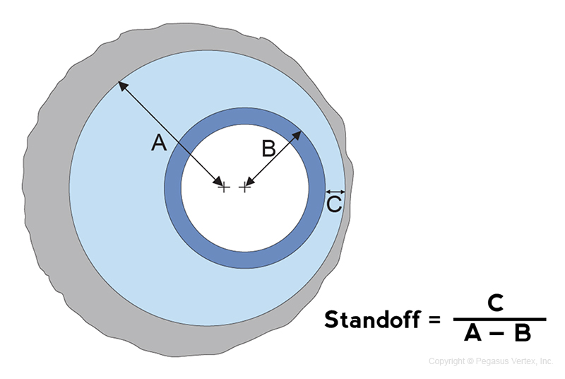
The term standoff (SO) describes the extent to which the pipe is centered (Fig. 1).

Fig. 1. Definition of standoff

Fig. 1. Definition of standoff

If a casing is perfectly centered, the standoff is 100%. A standoff of 0% means that the pipe touches the wellbore.  Regardless of the centralizer type, the goal is to provide a positive standoff, preferably above 67%, throughout the casing string.

The casing deflection between centralizers obeys the laws of physics. An engineering analysis can help both operators and service companies arrive at the optimized number and placement of centralizers for a particular well.

The casing standoff depends on the following factors:

  • Well path and hole size
  • Casing OD and weight
  • Centralizer properties
  • Position and densities of mud and cement slurries (buoyance)

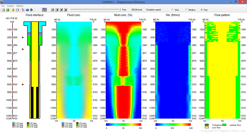
Incomplete mud removal causes poor cement seal and non-productive time.  A good casing standoff helps reduce the mud channeling and improves the displacement efficiency. The following 2 pictures illustrate the impact of casing standoff on displacement efficiency.  The 3rd track in Figure 3 shows the mud concentration in the annulus after a cementing job with 0% casing standoff.

Fig. 2. Displacement Efficiency for Casing Standoff of 0%

Fig. 2. Displacement Efficiency for Casing Standoff of 0%

You can see that there are some large red areas, which represent the high percentage of the remaining mud, in the narrow side (NS) of an eccentric annulus.

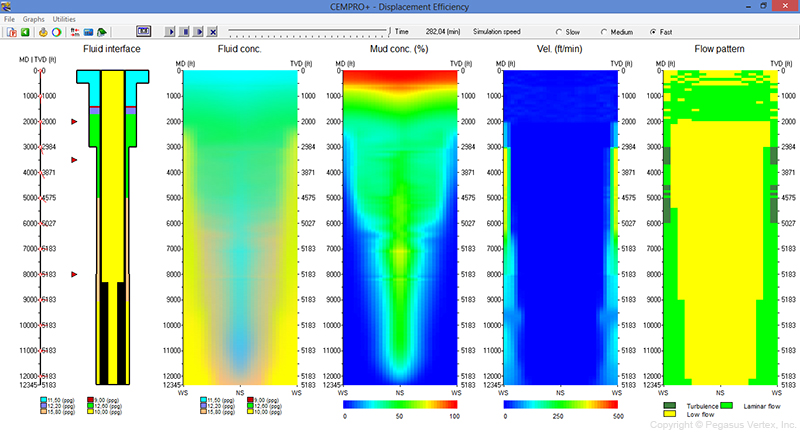
We kept everything else the same and only changed the casing standoff to 70%.  Now the displacement efficiency improved significantly, as shown in the following picture.

Fig. 3. Displacement Efficiency for Casing Standoff of 70%

Fig. 3. Displacement Efficiency for Casing Standoff of 70%

The Best is Yet to Come

The following is told by an American lady:

“My grandmother always used to tell us, “keep your forks.” when the main dishes were being cleared from the table. It was my favorite part of dinner, because I knew that something wonderful was coming… like a velvety chocolate cake or a deep-dish apple pie.”

A similar expression would be “You have not seen anything yet.” or as my 8-year old daughter told me, “I am not done yet!” when I gave her an applause after she sang the song from the movie “Frozen”.

Life is a simple and normal routine. Everyone has the same number of hours in a day and the same number of days in a year. It is up to us to make our daily routines more interesting, to fill our time doing things that will make us grow in every aspect of our lives, to make the most of our time. We cherish the hope that our present situation is not our final destination. The best is yet to come.

For us software developers, we are continuously enhancing the drilling software that is being developed. We certainly can’t add more hours to our day, but we can make our development more efficient. We will probably spend the same amount of time as we did last year, but we will have better products in 2014.

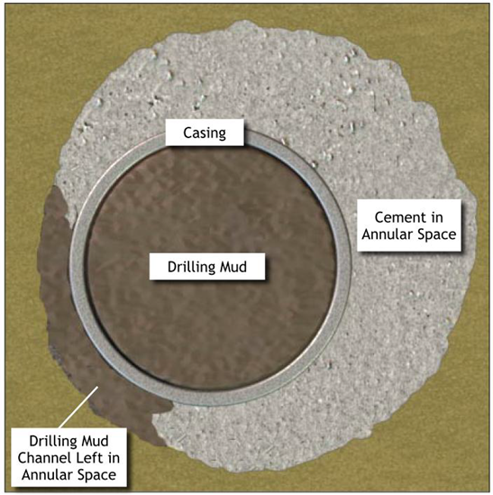
The latest release of our cementing software CEMPRO+ is a milestone. Why? Because this is the first time we address the displacement efficiency during the multi-fluid displacement operations such as cementing or wellbore cleanup. Before CEMPRO+ we used to assume that the drilling mud was completely displaced by the cement slurry with the use of a piston. This convenient assumption makes the hydraulics relatively easy, but it fails to predict the mud channeling which occurs due to many factors such as, differences in the cement properties and mud flow rates, and the casing centralization. A typical illustration of mud channeling is shown here:

Mud channel left on the narrow side of the annulus

Mud channel left on the narrow side of the annulus (Macondo incident-Chief Counsel’s report, 2011)

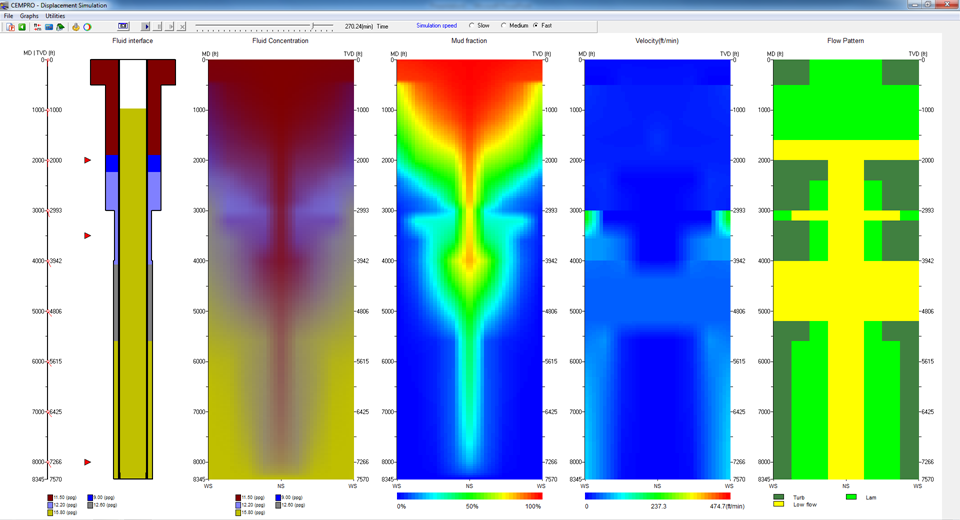
CEMPRO+ can help predict the mud fractions in the annulus during a cementing job. The following picture is a snap shot from the program. It looks neat. Graphics are more significant, because they show what really happens in the wide and narrow sides of the annulus.

Displacement Efficiency Illustration in CEMPRO+

Displacement Efficiency Illustration in CEMPRO+

If our CEMPRO has been on your software menu, keep your forks, because the best is yet to come.