In the realm of oil and gas extraction, setting a cement plug to seal off fluid movement in wells is a critical task. Whether it is for well abandonment or providing a starting point for sidetrack drilling, achieving a reliable seal demands precision and expertise.
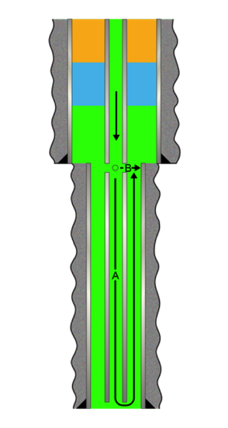
While the classic gravity-assisted balanced plug technique holds its own in vertical or moderately deviated wells, we're talking about a whole new ball game when it comes to horizontal or highly deviated holes. In those situations, it's time to pivot and explore alternative strategies. The industry successfully practiced the pump-and-pull method (Fig. 1). Unlike its gravity-dependent counterpart, pump-and-pull does not rely on gravity alone to spot the cement plug. Instead, the cementing crew pulls the pipe out of the hole while simultaneously pumping fluids into it. This approach offers superior control during plug placement, minimizing the risk of cement stringing out—an invaluable advantage in highly deviated or horizontal wells.
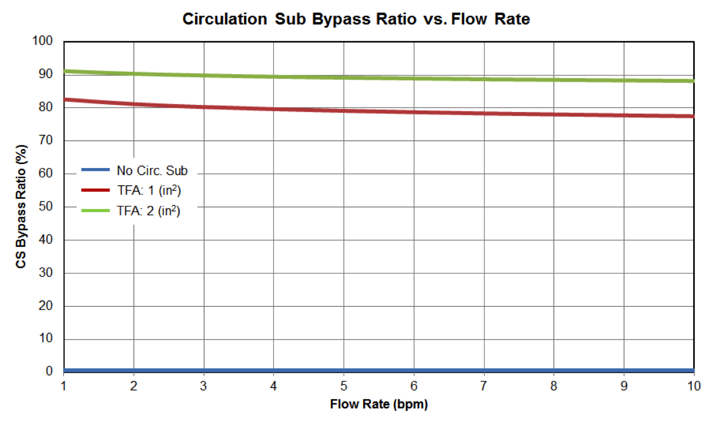
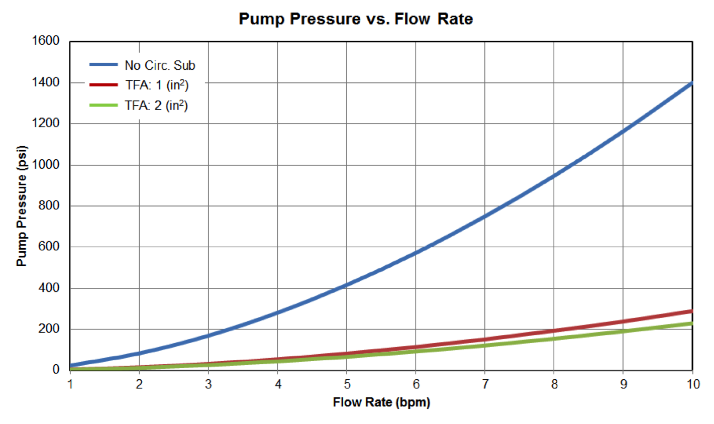
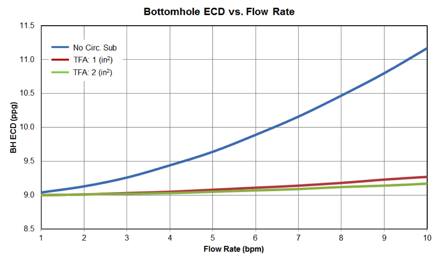
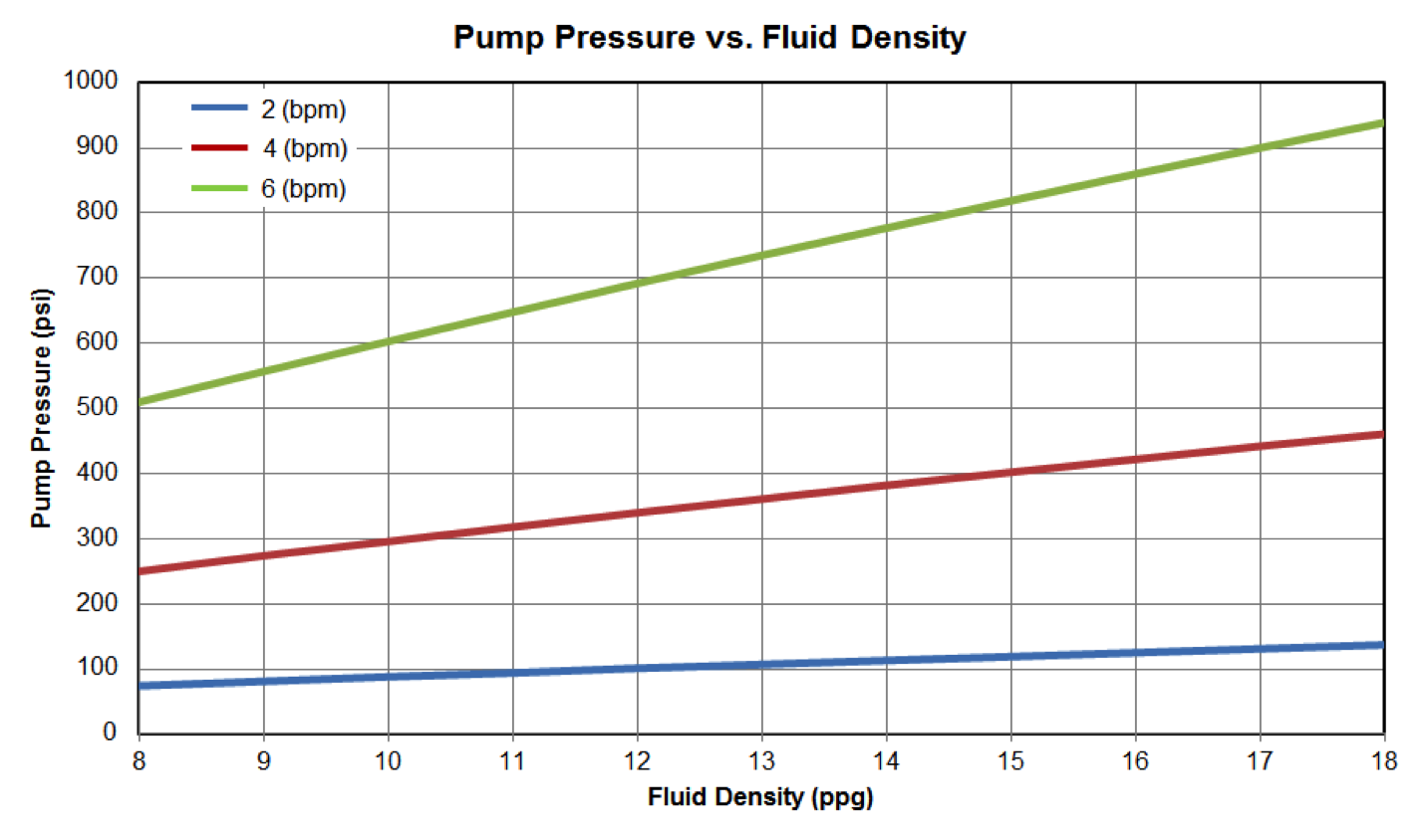
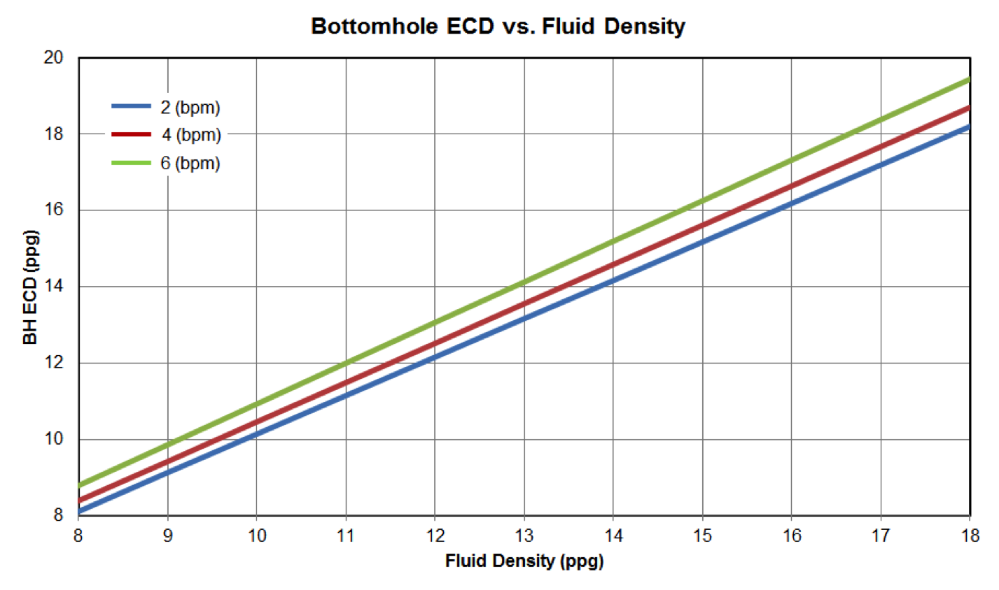
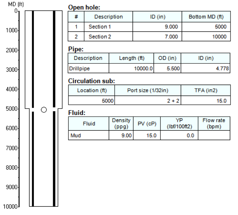
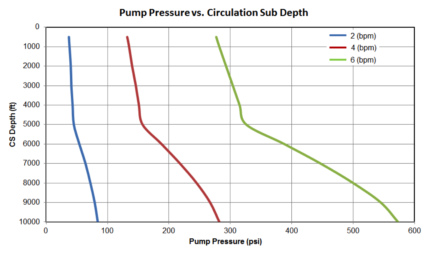
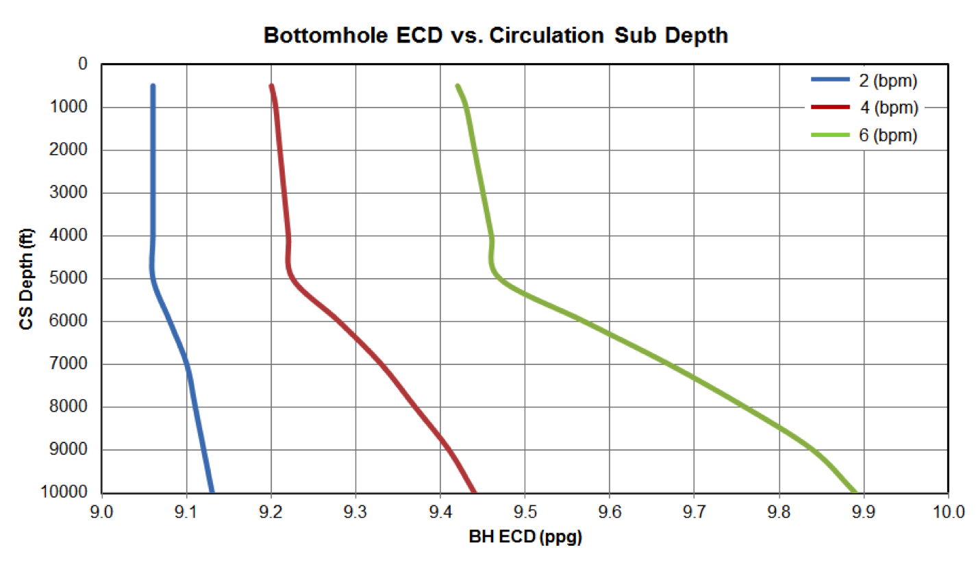
Let's face it, executing pump-and-pull jobs comes with its fair share of challenges. Synchronizing pulling speed with pumping rate is paramount to minimize contamination, making meticulous flow rate design critical. During the design phase, predicting fluid tops and slurry contaminations, along with calculating pumping pressure and downhole equivalent circulating density (ECD), are essential—but manually crunching these numbers in the face of complex wellbore structures, survey data, and pump sequences proves inefficient.
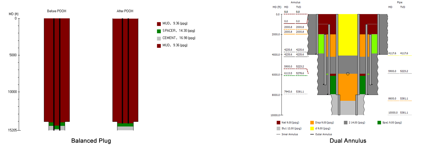
Enter PlugPRO – Cement Plug Placement software, a successful computer model in cementing design. PlugPRO introduces an innovative "pump-and-pull" feature alongside its existing balanced plug and dual annulus methods (Fig. 2), empowering engineers to tackle complex plug jobs with confidence.
This feature offers three distinct options for pump-and-pull simulation, catering to various operational scenarios:
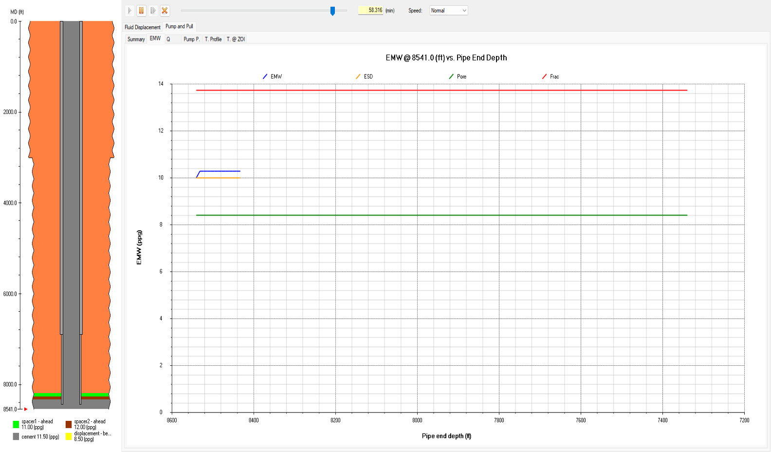
1. Sacrificial Cement: This method involves initially pumping a controlled amount of cement into the annulus before initiating the pump-and-pull operation (Fig. 3). The synchronization of pulling speed and pumping rate is crucial to effectively mitigate contamination risks in this method.
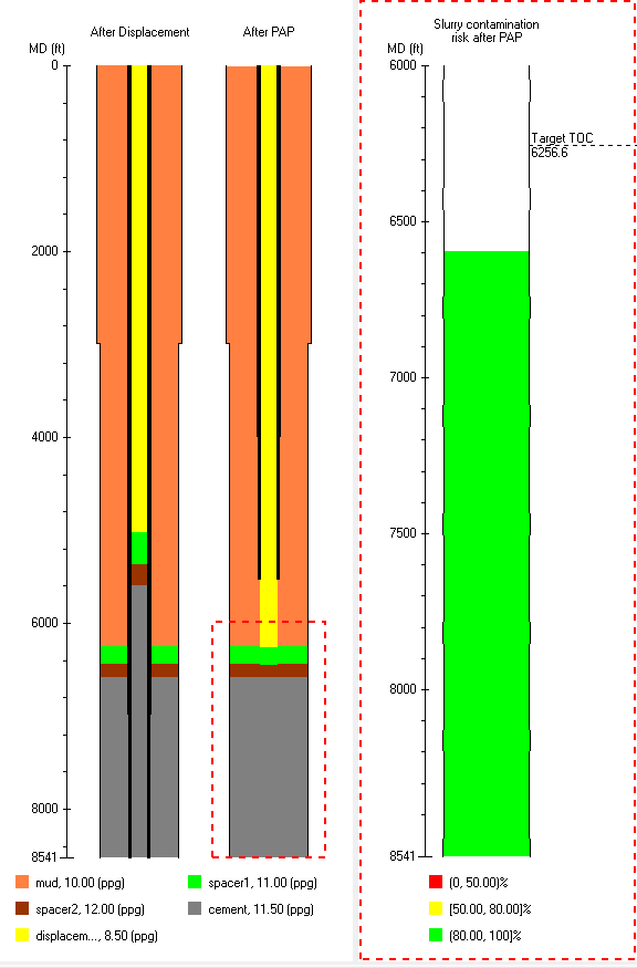
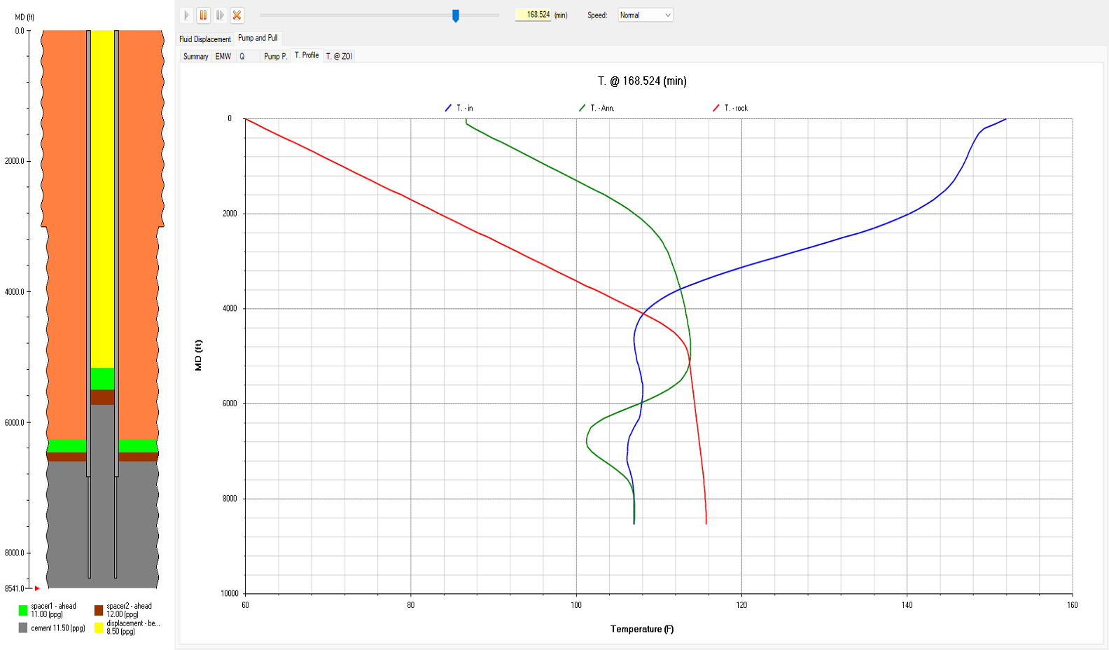
2. Pump and Pull after Cement Placement: Tailored for open holes, this method allows for the displacement of a significant portion of the cement slurry to the desired plug top, with the stinger positioned at the bottom depth of the cement (Fig. 4).
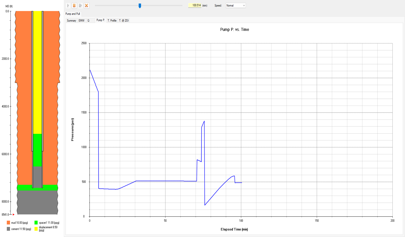
3. User-Defined Pump-and-Pull: Providing unmatched flexibility, this option empowers engineers to customize pump-and-pull sequences according to specific operational requirements (Fig. 5). By doing so, engineers can gain a comprehensive understanding of progress and identify any potential synchronization issues proactively.
PlugPRO now stands out as the go-to solution for enhancing pump-and-pull cementing operations. By precisely computing essential results such as fluid tops, pump pressure, ECD, temperature, and more, it empowers engineers with the tools they need to carry out their tasks with precision and confidence. With PlugPRO at their disposal, professionals can rely on the dependability and effectiveness of their cementing jobs, guaranteeing favorable results in the field.
Ready to take your plug jobs in cementing to the next level? Watch the video below to learn the Pump-and-Pull methods mentioned in this article and start mastering your technique.
For more information on the features of PlugPRO, visit our website:
www.pvisoftware.com/plugpro-cement-plug-placement.html
Explore PlugPRO firsthand - contact us at info@pvisoftware.com to schedule a complimentary demo.
Let’s elevate your cementing operations together!