Return to Square One: A Round Trip without Reaching the Destination

Due to business, I had to make a trip to Saudi Arabia via Paris. It was uneventful from Houston to Newark, where I made connection. I boarded on the flight, the meal was delicious and I took a Benadryl, hoping I could get some sleep on the way to Paris.

While I dreamt, I heard the announcement, “Ladies and gentlemen, as we start our descent…” I woke up and was delighted to imagine that I would be in Paris in a few minutes. Looking at the lights below, I tried to locate the Eiffel Tower. Then, a suspicious feeling arose, it was too soon for us to arrive; we should land in Paris during the day time. Then I heard my neighbor, who had also just woken up, saying, “Why are we landing in Newark?”

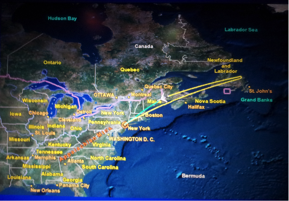
Finally, a flight attendant told us that 3 hours after the airplane took off, as we were just above the Atlantic Ocean, they found some issues with one of the engines. The captain decided to return home. The following is our flight trajectory that night.

Although I am a frequent business traveler, this was my first time experiencing this. I had a meal in the air, took a nap, and then I was back to square one. After all, the airline company must have had its own justification to fly back, and it is better to be safe than sorry.

As a result of this incident, except extra fuel cost, the airline company had to pay for our hotel and meals during delays. Apparently, everyone in this trip lost 6 hours; moreover, it brought about much inconvenience. No one would enjoy these types of surprises. However, the big picture is that the decision on flying back may have saved hundreds of lives. I am certain that airlines are making efforts to ensure flight safety and punctuality.

Drilling operations are like flight missions. There is a destination we want to reach, which we call total depth (TD). We assemble drill pipes, tools and bit. We circulate drilling fluid, control the hook load and weight on bit (WOB) to penetrate. But things could go wrong: pipe may get stuck, circulation lost, or bit dulled. Like this trip, those problems are unpredictable.

What we can do is to engineer the operation more carefully to identify potential problems prior to drilling. With our best effort, we keep the problems under control, and then we can be at ease with the outcome.

Despite the cancelled flight, I had brief but good sleep in a hotel by the airport. The next night, I caught another flight. After dinner, I took another Benadryl. This time, I woke up in Paris!

Casing Wear Series – 1: Causes

During the drilling phase, the most costly component is the casing. On top of the expensive casing materials and the costs likely to be encountered in cutting, pulling and replacing a worn or damaged string, casing wear creates more serious problems for operators due to its potential catastrophic incidents such as oil spills, blow outs or loss of the well.

To analyze the forces behind casing wear, we need to study the torque and drag (T&D) of the drill pipe during drilling operations. The basic mathematical and physical model of T&D has not changed significantly since Johancsik et al. published their paper on T&D prediction. Pipe movements such as drilling ahead or tripping create drag, while rotation produces torque. The magnitude of T&D is determined by the combination of these two movements.

Since the so-called vertical well virtually does not exist (the whirring action of the bit always creates a micro-helical shape of the well path), the contact of the drill pipe and its tool joint with the casing ID is unavoidable. The gravitational force acting on the drill pipe is always trying to pull the pipe to the lower side of the wellbore, while the axial tension on the drill pipe (in a build-up section) tends to push the pipe to the upper side of the wellbore. Depending on the pipe weight, dogleg severity, and axial force along the pipe, the drill pipe either touches the upper or lower side of the wellbore.

Typical T&D analysis starts by dividing the pipe into small elements. Calculation begins from the bottom element of the pipe, where weight on bit (WOB) and torque on bit (TOB) are expected. For each element, force and torque are balanced and the T&D at the top of the element are calculated. From bottom to top, calculations are performed for each pipe element, until it reaches the rig floor. This step-by-step calculation also determines the direction and magnitude of the side force, which pushes the drill pipe against the wellbore as shown in Figure 1.

Figure 1. Snapshot of Side Force along a Drill Pipe

Figure 1. Snapshot of Side Force along a Drill Pipe

Under this side force, the rotating tool joint on the drill pipe against the casing inside, gradually removes steel from the casing wall and forms a crescent-shaped wear on the casing as shown in Figure 2.

Figure 2. Rotating Tool Joint Wears Crescent Grooves in Casing

Figure 2. Rotating Tool Joint Wears Crescent Grooves in Casing

The seriousness of friction between two contacting surfaces is dependent on the nature of the rubbing surfaces and the mud.

The tool joint coating plays a bigger role here compared to the casing wall. The industry has seen tool joint coating evolve from “casing killer” (rough tungsten carbide) to “casing friendly” as shown by many high-tech hardbanding materials.

Tungsten carbide is applied on the tool joint. While it is a very good protector of the tool joints, it aggressively wears the casing so much that the mud type and its additive will not help much in reducing casing wear if rough tungsten carbide is present.

Once a casing friendly tool joint coating has been selected, the mud type and its additives play an intermediate role in casing wear. Water-based mud causes twice as much casing wear as the oil-based alternative. Lubricant reduces friction and severity of the wear.

Generally speaking, high dogleg will create a high side force and severe casing wear. The wear profile resembles the shape of dogleg severity. Higher RPM and lower ROP make more rotation time between the tool joint and casing and will cause aggressive wear.

The following conditions contribute to casing wear:

  • Well path and dogleg
  • Drill pipe weight
  • Tool joint coating
  • Mud and additives
  • RPM and ROP