Prediction Technique

Drillstring drag is the cumulative force required to move the pipe up or down inside the hole. Torque is the movement required to rotate the pipe. Drag forces usually are paralleled to the string weight measured with the string rotating but not reciprocating. Measured from the rotating string weight, the pickup drag is usually vaguely greater than the slack-off drag. The magnitudes of torque and drag are related in any particular well; high drag forces and excessive torque loads usually occur together. There are various causes for excessive torque and drag, such as tight hole conditions, keyseats, differential sticking, sloughing hole, sliding wellbore friction and cuttings buildup caused by poor hole cleaning.

With the exception of sliding friction, these causes are associated with problem conditions in the wellbore. Contrarily, in wells with great hole conditions, the primary source of torque and drag is sliding friction. Torque and drag from any source tend to be more troublesome in extended-reach directional wells. In very deep, highly deviated wells, overcoming torque and drag can be vital to the successful well completion. The capability to predict frictional loads on drillpipe has two main benefits:

  1. Deep, highly deviated wells can be planned to minimize torque and drag and ensure successful drilling operations to total depth.
  2. A more complete knowledge of drillstring loading allows use of improved drillstring design techniques, having considered the extra forces involved.

Both torque and drag are assumed to be caused entirely by sliding friction forces that result from contact of the drillstring with the wellbore. Two factors affect sliding wellbore friction:

  1. The normal contact force
  2. The coefficient of friction between the contact surfaces

The product of these two factors represents the magnitude of the sliding friction force. The normal contact force between the pipe and hole wall depends on several factors such as, the effects of gravity on the pipe, the effects of tension acting through curvatures in the wellbore and even pipe bending. The sliding friction coefficient is the ratio of the friction force to the normal contact force. This factor depends on specific contacting materials and on the degree of lubrication at various places in the wellbore. However, the oil and gas industry has made many advancements technologically speaking and quite a few models have been developed for these kind of issues.

PVI’s torque and drag model, TADPRO, is designed to help remove many of the risks of a drilling program, completions design or specific tool operations. Limits in the length of a horizontal based on specific friction factors can be determined. It can evaluate the needed weight to a liner-top packer. TADPRO can analyze forces downhole and predict rig equipment specifications for torque and hookload. The model provides both versatility and accuracy in its calculations and it integrates advanced features that make it easier for our users to use.TADPRO - Torque and Drag Drilling Software
Casing Wear Series – 1: Causes

During the drilling phase, the most costly component is the casing. On top of the expensive casing materials and the costs likely to be encountered in cutting, pulling and replacing a worn or damaged string, casing wear creates more serious problems for operators due to its potential catastrophic incidents such as oil spills, blow outs or loss of the well.

To analyze the forces behind casing wear, we need to study the torque and drag (T&D) of the drill pipe during drilling operations. The basic mathematical and physical model of T&D has not changed significantly since Johancsik et al. published their paper on T&D prediction. Pipe movements such as drilling ahead or tripping create drag, while rotation produces torque. The magnitude of T&D is determined by the combination of these two movements.

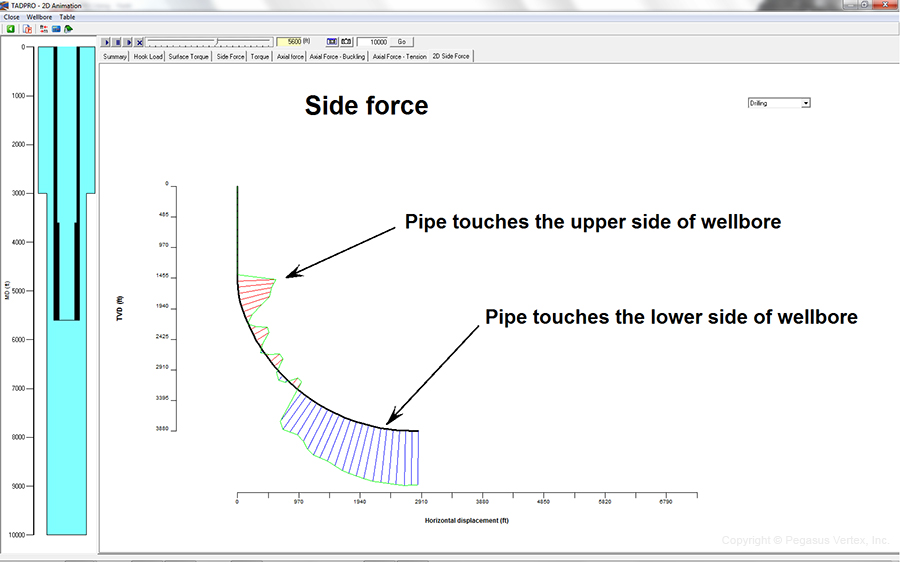
Since the so-called vertical well virtually does not exist (the whirring action of the bit always creates a micro-helical shape of the well path), the contact of the drill pipe and its tool joint with the casing ID is unavoidable. The gravitational force acting on the drill pipe is always trying to pull the pipe to the lower side of the wellbore, while the axial tension on the drill pipe (in a build-up section) tends to push the pipe to the upper side of the wellbore. Depending on the pipe weight, dogleg severity, and axial force along the pipe, the drill pipe either touches the upper or lower side of the wellbore.

Typical T&D analysis starts by dividing the pipe into small elements. Calculation begins from the bottom element of the pipe, where weight on bit (WOB) and torque on bit (TOB) are expected. For each element, force and torque are balanced and the T&D at the top of the element are calculated. From bottom to top, calculations are performed for each pipe element, until it reaches the rig floor. This step-by-step calculation also determines the direction and magnitude of the side force, which pushes the drill pipe against the wellbore as shown in Figure 1.

Figure 1. Snapshot of Side Force along a Drill Pipe

Figure 1. Snapshot of Side Force along a Drill Pipe

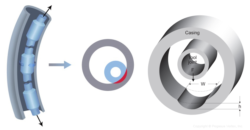
Under this side force, the rotating tool joint on the drill pipe against the casing inside, gradually removes steel from the casing wall and forms a crescent-shaped wear on the casing as shown in Figure 2.

Figure 2. Rotating Tool Joint Wears Crescent Grooves in Casing

Figure 2. Rotating Tool Joint Wears Crescent Grooves in Casing

The seriousness of friction between two contacting surfaces is dependent on the nature of the rubbing surfaces and the mud.

The tool joint coating plays a bigger role here compared to the casing wall. The industry has seen tool joint coating evolve from “casing killer” (rough tungsten carbide) to “casing friendly” as shown by many high-tech hardbanding materials.

Tungsten carbide is applied on the tool joint. While it is a very good protector of the tool joints, it aggressively wears the casing so much that the mud type and its additive will not help much in reducing casing wear if rough tungsten carbide is present.

Once a casing friendly tool joint coating has been selected, the mud type and its additives play an intermediate role in casing wear. Water-based mud causes twice as much casing wear as the oil-based alternative. Lubricant reduces friction and severity of the wear.

Generally speaking, high dogleg will create a high side force and severe casing wear. The wear profile resembles the shape of dogleg severity. Higher RPM and lower ROP make more rotation time between the tool joint and casing and will cause aggressive wear.

The following conditions contribute to casing wear:

  • Well path and dogleg
  • Drill pipe weight
  • Tool joint coating
  • Mud and additives
  • RPM and ROP

One Hundred Percent

"I'll take fifty percent efficiency to get one hundred percent loyalty."
- Samuel Goldwyn (American Producer)

It’s well known that time and cost overruns are very common in the oil and gas industry. As a matter of fact, most projects deal with one or both problems, yet there is an alternative: the industry could reduce costs and accelerate projects by implementing advanced models that bring good benefits and are very efficient.

Being efficient means achieving maximum productivity with minimum wasted efforts and/or expenses.

For a company to have an effective way in its productivity there has to be a change that influences its efficiency; a change that identifies the difference between doing the right thing and doing things right.

In the beginning process of developing a software here at PVI, we put into consideration what is effective for our clients but more so, what is efficient. We think of what can be done to make our clients' workload lighter yet progressive. With our software, casing wear can be predicted, centralizer placement can be optimized, torque and drag can be calculated, mud reporting can be simpler, and many other things can be performed. One of our priorities is to produce a software that gives our clients their desired or intended result.

A software that’s efficient is a software capable of doing processes that save time, money and efforts. That's a good characteristic to have in a software, because it helps the companies that use it to be effective at getting results.

Efficient | Drilling Software - PegasusVertex, Inc.

Instead of just striving to design an effective software, we strive to design a software that is efficient at being effective. Similar to what Samuel Goldwyn stated, instead of taking 50% of efficiency, we intend to take 100% efficiency to get 100% of loyalty from our satisfied customers.

An Illustration and A Twisted Finger

Let’s illustrate in an easier way what torque and drag is:

Hold your index finger tightly in the fist of your other hand.

Now twist your finger.

Twist Your Finger and You Feel The Pain


Do you feel how your finger does not want to twist?

Yes!

You know why?

Because it's not built to be twisted.

The pain you feel is because of the torque you are putting on the joints.  - That's torque.

Do you feel how your finger resists the pull because you have a good grip on it with your fist? - That's drag.

Torque and drag can have a dramatic increase in horizontal and extended-reach wells and can become the limiting factor in determining the horizontal length or extended-reach of a well. For this reason, precise calculations of torque and drag are necessary for drilling operations. Torque and drag are the results of friction caused by a moving pipe inside the wellbore: torque occurs when rotating the pipe along the wellbore and drag occurs when moving the pipe.

When drilling horizontal or extended-reach wells, excessive torque and drag may become troublesome both in the drilling operations and later in the completion operations. Estimating torque and drag is very important, but the calculation of drag in the build section of a well is complicated by the effect of the axial force (tensile or compressive) on the lateral contact force which produces the sliding drag and in turn causes changes to the axial force itself. The axial force has a great effect on the torque and drag calculations in the build section. When the axial force (tension or compression) becomes large enough to let the pipe contact only one side of the wellbore, the torque and drag in the build section will increase proportionally with the increase in the axial force.

The most common way to calculate approximate torque and drag values in the build section involves monotonous numerical calculations: dividing the build section into many small pieces, assuming the axial force remains constant in those small pieces, calculating the friction factor for each of the pieces, and then summing these values to get the total drag over the entire build section. This process is both time-consuming and difficult for field engineers.

The analysis of torque and drag is made easier by today’s technology. There is a comprehensive torque and drag software in the market that removes many of the risks during the drilling process. This software was developed by PVI and it’s called TADPRO (Torque and Drag).

TADPRO - torque and drag

This software comes with features that help users to:

  • Calculate hookload and surface torque
  • Identify potential buckling
  • Perform sensitivity analysis
  • Determine side force
  • Analyze forces downhole
  • User-friendliness and graphical outputs

Illustrations have always been a great learning method and today we have learned two things:

  1. Fingers were not made to be twisted.
  2. Likewise a pipe is not built to be twisted, but the torque and drag inevitably occurs during horizontal drilling, but with the help of TADPRO, torque and drag can be calculated and predicted, therefore the risks are reduced.

A Phrase of Being Stuck

Jill Scott said:

“I need to find a creative diversity because if I get stuck, I get unhappy.”

At times we all find ourselves stuck in different aspects of our lives.  Maybe not for the same reason; sometimes it could be fear, guilt, nostalgia and even boredom, but the result is the same.

We’re stuck.

But then, how can we get out of it? How do we get unstuck? The answer is very simple: “we find the problem and along with it, we find the solution”. Let’s take this example and apply it to the drilling process.

During a drilling operation, if a pipe cannot be freed from the hole without causing any damages to the pipe and without exceeding the drilling rig’s maximum hook load this is considered a stuck pipe. Pipe sticking can be classified under two categories:

  1. Differential pressure pipe sticking
  2. Mechanical pipe sticking

When having complications due to a stuck pipe this can be nearly half of the total cost of the well, making stuck pipe one of the most expensive problems that can occur during a drilling operation and is a serious risk in high-angle and horizontal wells.

Drilling through depleted zones, where the pressure in the annulus surpasses that in the formation, might cause the drillstring to be pulled against the wall and embedded in the filter cake deposited there. The internal cake pressure diminishes at the point where the drillpipe contacts the filter cake, causing the pipe to be held against the wall by the differential pressure. In high-angle and horizontal wells, the gravitational force contributes to prolonged contact between the drillstring and the formation.

What are some of the mechanical causes for stuck pipe?

  • Keyseating
  • Packoff from poor hole-cleaning
  • Shale swelling
  • Wellbore collapse
  • Plastic-flowing formation (i.e., salt)
  • Bridging

What are some of the signs that need to be monitored to prevent stuck pipe?

  • Increasing in torque and drag
  • Excessive cuttings loading
  • Tight spots while tripping
  • Loss of circulation while drilling

Depending on what the suspected cause of sticking is, it is necessary to act properly and urgently.

There is a tool developed by PVI Called StuckPipePro, which is a stuck pipe analysis that every operator should have to reduce the risks of pipe sticking to the minimum. This effective tool is equipped with great features, for example: stuck chance calculation, free point calculation, back-off force calculation, stuck pipe mechanism, which assist in determining the mechanism that is actually behind the stuck pipe situation and which technique should be used to free the pipe. It also comes with a decision flow chart that guides users through a series of questions to find the cause of pipe sticking.

StuckPipePro - Stuck-pipe-analysis

StuckPipePro - Stuck Pipe Analysis

Just like the phrase of being stuck said by Jill Scott; once we find the problem, we’ll find the solution, in this case, with StuckPipePro.

Horizontal Drilling and TADPRO

There is a good saying in oil drilling area: “Oil’s been found where it’s been found before.” This sentence has been proven to be so true again by the recent booming of oil drilling industry around USA.

A new drilling surge is happening around USA this year. Some people called it a “miracle”. Indeed it is a miracle due to the highly developing drilling technology. Horizontal drilling and fracking are two contributors to this miracle. Now in Houston, we saw that the energy companies, oilfield contractors and even landowners are rushing again into the profitable drilling industry.

Horizontal drilling is not a new thing. This drilling technique has been a hot topic for engineers and researchers for a while, but not been widely applied until 2003. Horizontal drilling is defined in Lynn Helm’s paper as "Horizontal Drilling": "Horizontal drilling is the process of drilling a well from the surface to a subsurface location just above the target oil or gas reservoir called the “kickoff point”, then deviating the wellbore from the vertical plane around a curve to intersect the reservoir at the “entry point” with a near-horizontal inclination and remaining within the reservoir until the desired bottom hole location is reached." Horizontal drilling has been going on for years in other states besides Texas around the country, including Colorado, Wyoming, New Mexico and Alabama.

However, extended-reach directional wells are becoming more prevalent today, which means that tubulars are exposed to greater amounts of torque and drag (T&D). If this torque and drag is not evaluated properly, it’ll result in stuck pipe, pipe failures and costly fishing jobs, not even mention the effects of environment contamination.

TADPRO, a comprehensive torque and drag software developed by PVI helps remove many risks of drilling program, completion design and specific tool operation. Limits in the length of a horizontal based on specific friction factors can be determined. The ability to get needed weight to a liner-top packer can also be evaluated. With the ability to analyze forces downhole, rig equipment specifications for torque and hookload can be predicted.

With unparalleled user-friendliness and graphical outputs in the industry, TADPRO provides both versatility and accuracy in its calculations, while also integrating advanced features that make it extremely easy to use and interpret results.

Although horizontal drilling didn't draw as much attention as "fracking", it is a marvel that truly benefits the drillers, just as drilling software does.

Horizontal Drilling And Tadpro Pegasus Vertex

Friction: Drilling Engineers’ Friend and Foe

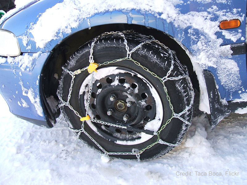
Friction, the resistance force between two rubbing surfaces, the very drag consumes our energy while we walk, run and drive, also prevents us from falling, colliding and accident.

Friction is everywhere. We can see it painting on roads when car makes sudden stop. We can hear it screaming when wheels stop rotating while car keeps the momentum. We can smell its anxiety when Native Indians rotate drive in wood making fire. These are some appearances of friendly sides of friction. And sometimes, we need to amplify its power by the means like the following.Friction: Drilling Engineers’ Friend and Foe


For downside, we have seen plenty in our daily lines. Our shoe wears out (so our feet do not). We dress smart phone up by putting screen or cover so that scratch (a form of friction) only damages the dress, not the body.

This is friction: we hate, love and cannot get rid of it. And we had better use it toward our advantage.

In drilling and completion practices, we encounter friction whenever we move tubular inside wellbore. When moving pipe downward such as in drilling and casing running, friction slows us down. If we move pipe upward such as in trip-out, friction is pulling pipe down. Yes, friction always acts in the opposite direction of the moving object.

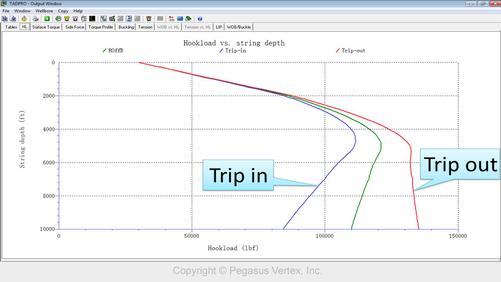
In torque and drag analysis, one graph is worth noting: the hookload for trip-in and trip-out operations, as shown here.

Drilling Software and Friction Pegasus Vertex Inc


The green line is the hookload when pipe is stationary inside wellbore at various depths.

The blue line shows the hookload when pipe is moving downward. The red line is the hookload when pipe is moving upward.

Note that during trip-in, the frictional drag is against the gravitational force, so the hookload is smaller than the hookload during trip-out, when the frictional drag acts with the gravitational force.

In other words, during trip-in, friction helps hook to hold the pipe weight, while during trip-out, the friction is on the same side of gravitation to make hookload higher.

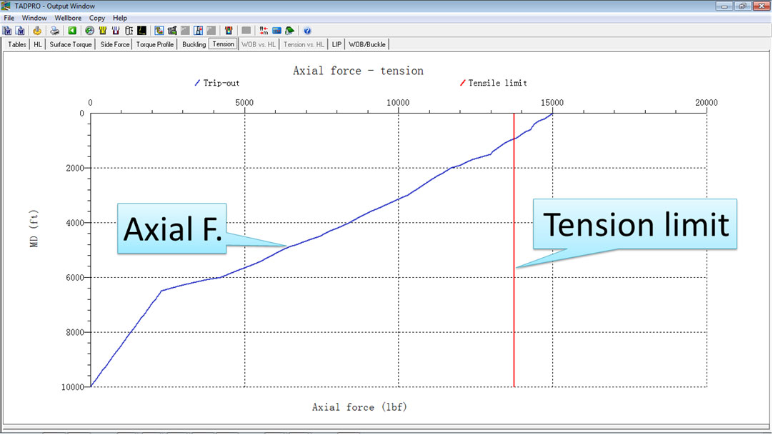
For coiled-tubing (CT) operation, since CT has relatively thin wall (could be as small as 0.125 inch), the tensile limit of CT may not withstand the pulling of drag and weight during trip-out, as shown in the following graph.

Drilling Software And Friction Pegasus Vertex Inc.


We can run the CT into a deviated well. However, we may not be able to pull the same CT out of the hole!

Friend or foe, friction shows up in various fashions. We just need to know his characteristics and dance with him.

Drilling Software: A Bridge between Research Efforts and Field Executions

The term R&D or research and development refers to a specific group of activities within a business. There are 2 main goals of an R&D project: develop new products and discover/create new knowledge.

In our drilling community, we have seen many R&D projects with various sizes and duration. Petroleum engineering departments of many universities receive grants from industry and conduct specific tasks. On a big scale, joint industry projects (JIP) gather resources from different companies, both operators and service providers. I was involved in some big JIP projects such as DEA-44 (Horizontal Technology), DEA-42 (Casing Wear Technology) etc. By the way, DEA here stands for Drilling Engineering Association, not Drug Enforcement Administration. Many R&D projects produce great know-how and sometimes prototype products. However, we need a vessel to package the knowledge from these R&D efforts.

Software naturally becomes the form to hold the knowledge. With graphical user interface (GUI), it can become a powerful tool for end users, who often are not involved in the project.

An R&D project without action is incomplete. A software package serves as a bridge between the gap of research results and field executions. For example, not many people understand how the equation of force balance is used to calculate torque and drag along a drill string or casing, but most drilling engineers understand the hook load and surface torque charts. As a matter of fact, we don’t have to be able to solve numerical equations to be drilling engineers. The advanced engineering and calculation capabilities are already packed in the ready-to-use software like TADPRO (torque and drag model).

If not for exercising purpose, you probably want to ride to office than walk. You probably want to take bridge than take boat to reach the other end.

Let our drilling software help you drill more efficiently.

Software: Drilling Engineers’ Eyes

Oil well drilling is one of the most fascinating engineering collaborations I have ever come across. It requires efforts from drill bits, tubulars, motors, mud and the list goes on. Most impressively, all of the drilling processes take place under the ground, probably tens of thousand of feet, maybe horizontally, away from the rig.

To keep drilling operations under control, people have developed many technologies that incorporate electronic, magnetic, and radioactive methods in order to understand the formation and downhole conditions.

The following picture shows a giant, floating iceberg. For a typical iceberg, only 10% of its mass is visible above the water. The remaining 90% is immersed in the deep blue.

It is difficult to estimate its underwater shape; hence, we say “tip of iceberg“ meaning the starting sign of problem.

Similar situations exist on rig floors. Drillers have limited information, which include hook load, surface torque, etc. However, they do not know the axial force along the string, whether the pipe is buckled or not, or if the torque on the pipe connection exceeds the makeup limit. Experienced drillers may sense the downhole problems through the combination of brake vibration, noise or pump pressure, etc., but what we need is something to bridge the gap between what we can see and what we cannot see.

Drilling software servers as this bridge!

Over the past 20 years, drilling engineering software has become an indispensable engineering tool in design phases, real-time monitoring and post job analyses. Using known operation parameters such as ROP, RMP, mud weight, drilling string configuration and well path trajectory, software like TADPRO can predict pipe buckling, hook load, surface torque, etc.

In other words, software is becoming drilling engineers’ eyes. Equipped with software, we can not only understand what we see (why certain hookload, surface torque), but also see the otherwise invisible happenings.

Do you have “eyes“ for your next well?

Torque and Drag - Nuts and Bolts

No matter it is an operation of drilling or casing running; any pipe movement in the deviated wellbore produces torque and drag (T&D) along the pipe. T&D is our weapon to drill a well or run a casing to the bottom. However, excessive T&D will cause equipment and operation failure.

Basically, axial movements such as drilling ahead or tripping creates drag, while rotation produces torque. The magnitude of T&D is determined by the combination of these two movements. Rotation shifts the resistance from drag to torque. In other words, you can shift the drag to torque by rotating the pipe. That is why people tend to rotate the pipe little bit if pipe gets stuck.

Torque and Drag Calculation

Typical T&D analysis starts by dividing the pipe into small elements. Calculation begins from the element at the bottom of the pipe, where weight on bit (WOB) or torque on bit (TOB) is expected. For each element, force and torque are balanced and the T&D at the top of the element are calculated step by step and from bottom to top, calculation is performed for each pipe element, until it reaches the rig floor. We call the torque and drag at the top of pipe surface torque and hook load (with block weight), respectively.

Torque and drag calculationTorque and Drag Common Terms

Some terms often used in torque and drag analysis are listed here with explanations:

  • Friction Factor (F.F.) - the representation of the friction between the wellbore/casing and the work string. The friction factor is dependent on mud type, pipe and wellbore and cutting concentration. Higher cutting concentration leads to higher friction factor.
  • Rotating Off Bottom (ROffB) – pipe rotates without any axial movement, such as rate of penetration or tripping. There is no WOB or TOB because bit is not engaged with formation.
  • Rotating On Bottom (ROnB) – pipe rotates without any axial movement, such as rate of penetration or tripping. However, WOB and TOB are present because bit is engaged with formation.
  • Drilling – pipe rotates with certain rate of penetration and with the presence of WOB and TOB.
  • Slide Drilling - Drilling with no drill string rotation. (only axial movement, no rotation)
  • Sinusoidal Buckling - Sinusoidal buckling occurs when compressive forces on the string become too high, resulting in a snake-like bending in the string. Note that in this mode, the pipe deforms, but still in a 2D plan.
  • Helical Buckling - a more extreme form of buckling which occurs when compressive forces pass through sinusoidal buckling and exceed the helical buckling limit. Helical buckling causes contact between the pipe and the wellbore, exerting force on the wall of the hole. Both drill string fatigue and interference with weight transfer to the bit occur. Helical buckling should be avoided.
  • Helical Lockup - Helical lockup occurs when compressive forces on a string in helical buckling prevent axial movement. Forces at surface are not transmitted to the bit.
  • Tension Limit- The tension limit of a material is based on its yield strength, which is measured in psi. When the minimum yield strength is exceeded, pipe will plastically deform. Plastic deformation occurs when pipe that has stretched does not return to its original shape.
  • Make Up Torque- The rotational force used to make up a connection in the string. Drill pipe failure may occur when the make-up torque of a connection is exceeded.Buckling-Tension-Torsion
  • Stress in the String - The various stress that TADPRO models are axial, bending, torsional, and shear stresses. These stresses are summed up in the Von Mises Stress. Various failures occur as a result of repeated stress to a string, including cracking, washouts, and twist offs, etc.
  • Stress in the String - The various stress that TADPRO models are axial, bending, torsional, and shear stresses. These stresses are summed up in the Von Mises Stress. Various failures occur as a result of repeated stress to a string, including cracking, washouts, and twist offs, etc.
  •  Casing Wear- Prolonged, repeated axial and rotational movement within casing will wear both at the string and the casing, potentially leading to string and casing failure.Casing wear