Casing Wear Series – 1: Causes

During the drilling phase, the most costly component is the casing. On top of the expensive casing materials and the costs likely to be encountered in cutting, pulling and replacing a worn or damaged string, casing wear creates more serious problems for operators due to its potential catastrophic incidents such as oil spills, blow outs or loss of the well.

To analyze the forces behind casing wear, we need to study the torque and drag (T&D) of the drill pipe during drilling operations. The basic mathematical and physical model of T&D has not changed significantly since Johancsik et al. published their paper on T&D prediction. Pipe movements such as drilling ahead or tripping create drag, while rotation produces torque. The magnitude of T&D is determined by the combination of these two movements.

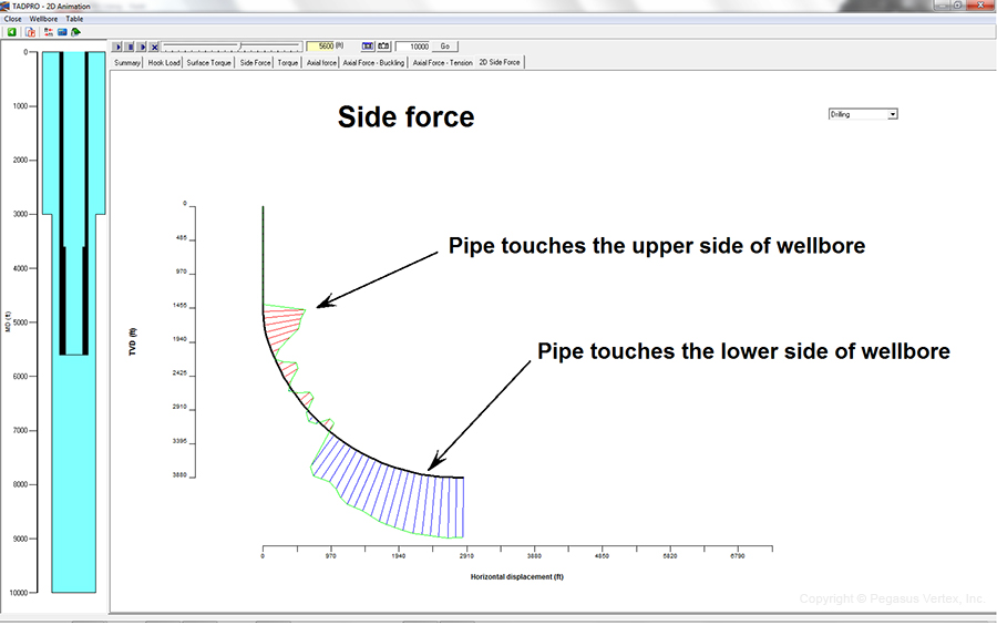
Since the so-called vertical well virtually does not exist (the whirring action of the bit always creates a micro-helical shape of the well path), the contact of the drill pipe and its tool joint with the casing ID is unavoidable. The gravitational force acting on the drill pipe is always trying to pull the pipe to the lower side of the wellbore, while the axial tension on the drill pipe (in a build-up section) tends to push the pipe to the upper side of the wellbore. Depending on the pipe weight, dogleg severity, and axial force along the pipe, the drill pipe either touches the upper or lower side of the wellbore.

Typical T&D analysis starts by dividing the pipe into small elements. Calculation begins from the bottom element of the pipe, where weight on bit (WOB) and torque on bit (TOB) are expected. For each element, force and torque are balanced and the T&D at the top of the element are calculated. From bottom to top, calculations are performed for each pipe element, until it reaches the rig floor. This step-by-step calculation also determines the direction and magnitude of the side force, which pushes the drill pipe against the wellbore as shown in Figure 1.

Figure 1. Snapshot of Side Force along a Drill Pipe

Figure 1. Snapshot of Side Force along a Drill Pipe

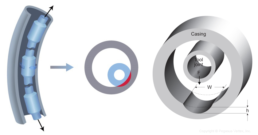
Under this side force, the rotating tool joint on the drill pipe against the casing inside, gradually removes steel from the casing wall and forms a crescent-shaped wear on the casing as shown in Figure 2.

Figure 2. Rotating Tool Joint Wears Crescent Grooves in Casing

Figure 2. Rotating Tool Joint Wears Crescent Grooves in Casing

The seriousness of friction between two contacting surfaces is dependent on the nature of the rubbing surfaces and the mud.

The tool joint coating plays a bigger role here compared to the casing wall. The industry has seen tool joint coating evolve from “casing killer” (rough tungsten carbide) to “casing friendly” as shown by many high-tech hardbanding materials.

Tungsten carbide is applied on the tool joint. While it is a very good protector of the tool joints, it aggressively wears the casing so much that the mud type and its additive will not help much in reducing casing wear if rough tungsten carbide is present.

Once a casing friendly tool joint coating has been selected, the mud type and its additives play an intermediate role in casing wear. Water-based mud causes twice as much casing wear as the oil-based alternative. Lubricant reduces friction and severity of the wear.

Generally speaking, high dogleg will create a high side force and severe casing wear. The wear profile resembles the shape of dogleg severity. Higher RPM and lower ROP make more rotation time between the tool joint and casing and will cause aggressive wear.

The following conditions contribute to casing wear:

  • Well path and dogleg
  • Drill pipe weight
  • Tool joint coating
  • Mud and additives
  • RPM and ROP

Like The Barriers on The Road

This is a story about a town located at the bottom of a deep valley.

The Vally

The only road into town was steep and windy, barely hanging on to the steep mountain-side surrounding the town. Very often, cars traveling into town would get too close to the edge of the road and tumble into the valley. Over time, the town spent hundreds of thousands of dollars responding to wrecks and they got tired of going out to respond to the same thing over and over. The town’s people rendezvoused to discuss the matter and how to solve it. Some folks thought they should ignore what was happening and let people fend for themselves. Others thought they should continue to help the people who went off the road, but should charge them for the costs involved. A few suggested that they should just close the road so those strangers wouldn't cause them any more problems. The majority of the people quickly acknowledged that the road posed a risk for strangers but also for friends, family and the townspeople themselves. Since nobody agreed to a specific solution, one person suggested they put up a barrier on the edge where cars most often went off the road and everybody agreed and so they did. Over the years, the barrier cost the community far less than all the rescuing they had been doing for so many years. A simple barrier was the solution.

It's a simple story, but a great metaphor for prevention. Like the barriers on the road, for more than 6 decades, casing centralization has been established as being essential to efficient mud removal and therefore to a successful cementing job. Prior to a production it is very common for field engineers to spend time improving casing centralization using software, particularly for highly deviated wells. However today, while long lateral wells are being drilled, they become more challenging in getting the casing to bottom and achieving good zonal isolation. That is why casing centralizers play a key role in achieving these objectives and should be evaluated differently than they have been in the past.

Predicting casing standoff is essential since not knowing where to locate the centralizers and how many are needed can cause several problems. The main reason for centralization is to ensure a uniform distribution of cement around the casing. No centralization or poor centralization will cause channeling of the cement and therefore produce poor cement adherence.

What do centralizers prevent?

  • When running a casing, the adequate use of centralizers reduces the chance of wall sticking.
  • In deviated wells because of the increased amount of support, the casing requires to stay in the center of the hole – especially in build-up sections - a more dense distribution of centralizers is required than in straight holes.

There are two main types of centralizer:

  1. Spring (Bow) Centralizers
  2. Rigid Centralizers

Spring (bow) centralizers are often used for vertical and deviated wellbores and rigid centralizers are used for horizontal wellbores. The method of installation for both of these depends entirely upon the centralizer design. However, care must be taken to ensure the quality of the cementing job. Centralizer placement is synonym of prevention.

For this PVI developed CentraDesign software that optimizes the centralizer placement, predicts casing standoff and torque and drag for extended reach drilling and deviated wellbores.

CentraDesign (Centralizer Placement)

CentraDesign also determines the number and placement of centralizers, hence providing both service companies and operators with a very sophisticated yet easy to use tool that will help prevent problems during the cementing process.

Prevention is like the barrier put up to keep cars from going over the edge and it works to keep unwanted things from happening in the first place.

Casing Wear Series - 2: The Basics

When it became apparent that casing wear was going to be a matter to be reckoned with, several organizations initiated experimental studies of this phenomenon. Among these were (1) Shell Oil Company, (2) Exxon, (3) Texas A & M, and (4) Drilco. All these operators discovered that experimental casing wear studies were both time consuming and expensive.

All of the casings wear studies involved building a machine that would simulate field conditions as closely as possible in the laboratory. Figure 1 is a symbolic presentation of a casing wear test machine that incorporates all of the parameters needed to simulate casing wear as it would occur under field conditions.

Elements-of-a-casing-wear-test-machine

Figure 1: Elements-of-a-casing-wear-test-machine

As shown in the Figure 1, the rotating tool joint sample is pressed against the inner wall of the casing sample with a constant force. The intersection of the casing and the tool joint is flooded with drilling fluid, which contains sand to simulate the drill cuttings which the mud transports to the surface in field operations.

In addition, the tool joint ( or the casing sample ) should be slowly reciprocated during the wear test to simulate drilling progress. Failure to include this reciprocation results in a significant reduction in the observed casing wear. It is believed that without reciprocation, the casing sample and the tool joint sample will `mate’ to each other, and the drilling fluid will then form a hydrodynamic lubricating layer between the two surfaces. This will greatly reduce the grinding effectiveness of the sand that is transported by the drilling fluid. Non-reciprocating wear tests may result in as little as 10% of the wear observed in tests where reciprocation is employed.

Such a casing wear test machine is pictured in Figure 2. This machine was built by Steve Williamson ( Drilco ) in the early 1980s, and was later purchased by Maurer Engineering for use in the Drilling Engineering Association ( DEA ) projects ( DEA – 8, DEA – 42, and DEA – 137 ). These projects covered the period from 1990 through 2002.

Drilco casing wear test machine

Figure 2: Drilco casing wear test machine

Most of the material presented in these articles was developed as a result of the work done using this machine.

Casing Wear Series - 1: How we got here?

Prologue

Mr. Gefei Liu, president of Pegasus Vertex, Inc. (PVI), suggested that I write a series of short articles to discuss the empirical science of casing and riser wear. PVI incorporates this technology in their computer program – ‘CWPRO’. This program applies wear technology to predict casing and riser wear to be expected during drilling operations.

The observations and opinions expressed in these articles are based on my 20-year association with the subject of casing and riser wear. Much of this time was spent at Maurer Engineering, under the direction of Dr. W. C. Maurer. Much of the advances in the subject were the direct result of Dr. Maurer’s phenomenal knowledge of and insight into the technical challenges that were encountered during the development and application of casing and riser wear technology.

In the beginning

Casing wear was not recognized as a problem until the early 1960s. Vertical wells were being drilled deeper, and directional wells were being pushed out further. This required longer drilling times, and resulted in much greater exposure of the inner wall of the intermediate casing to the rotating tool joints of the drill string. Wear grooves appeared in the intermediate casing and progressed from noticeable to serious.

Up to this time, tool joint wear was the only wear problem being treated.

The universally accepted treatment to prevent tool joint wear was to coat the tool joints with an alloy containing tungsten carbide particles. This protected the tool joints, but was proving to be a bit hard on the intermediate casings.

Tungsten carbide coated tool joint (Field Applied)

Figure 1: Tungsten carbide coated tool joint (Field Applied)

The tungsten carbide coated tool joints were efficiently machining wear grooves into the inner walls of the intermediate casings. As these wear grooves deepened, they would seriously reduce the pressure capacities (burst & collapse), sometimes resulting in catastrophic failure.

Pressure test of worn casing

Figure 2: Pressure test of worn casing

These early findings resulted in the establishment of two distinct, but related, developments.

1. Experimental studies of casing wear; and

2. The development of casing-friendly tool joint coatings that would also protect the tool joints.

First of all, what are the basic elements of casing wear?

If boreholes were straight, casing wear would be much less of a problem. But, boreholes are not straight. As shown in Figure 3, tension in the drillstring pulls the rotating tool joints into the convex sides of the curved borehole. Since the tension in the drillstring may be several hundred thousand pounds force, the lateral loads forcing the tool joints into the convex wall of the intermediate casing may be several thousands of pounds force. The greater the curvature of the borehole, measured as `dogleg severity’, the greater will be the lateral load pushing the drill string into the intermediate casing wall. ‘Dogleg Severity (DLS)’, which is measured in degrees per 100 feet, can run as high as 5 deg/100 ft. or worse.

Drilling fluid which transports drill cuttings to the surface, flows past the tool joint/casing contact, and provides the abrasive needed to grind a wear groove into the inner wall of the intermediate casing.

Casing wear at a dogleg is shown in Figure 3, and a schematic of the resulting casing wear groove is shown in Figure 4.

The existence of the casing wear grooves indicates that there are many locations where epicyclic drillstring vibrations do not occur.

Elements of casing wear

Figure 3: Elements of casing wear

Casing wear groove

Figure 4: Casing wear groove


"Being a deepwater well driller—what's it like?"

Source: excerpted from A Sea In Flames, published by Crown Publishers, New York.

On a recent trip to South Korea, I spent most of my time in the airplane reading Carl Safina’s non-fiction book “A Sea in Flame”. I liked it very much.  Among many things, the following section attracted my eyes, because it describes the deepwater drilling in a easy-to-understand format.

I contacted Carl Safina and got his permission to publish this section in our blog.

Pegasus


Being a deepwater well driller—what’s it like? To simplify, imagine pushing a pencil into the soil. Pull out the pencil. Slide a drinking straw into that hole to keep it open. Now, a little more complex: your pencil is tipped not with a lead point but with a drilling bit. You have a set of pencils, each a little narrower than the last, each a little longer. You have a set of drinking straws, each also narrower.

PencilYou use the fattest pencil first, make the hole, pull it out, then use the next fattest. And so on. This is how you make the hole deeper. At the scale of pencils-as-drills, you’re going down about 180 feet, and the work is soon out of sight. As you push and remove the pencils, you slide one straw through another, into the deepening hole. You have a deepening, tapering hole lined with sections of drinking straw, with little spaces between the hole and each straw, and between the sections of straw.

You have to seal all those spaces, make it, in effect, one tapering tube, absolutely tight. And here’s why: the last, narrowest straw pokes through the lid of a (very big) pop bottle with lots of soda containing gas under tremendous pressure. As long as the lid stays intact and tight, there’s no fizz. But only that long. Everyone around you is desperate for a drink of that pop, as if they’re addicted to it, because their lives depend on it. They’re in a bit of a hurry. But you have to try to ignore them while you’re painstakingly working these pencils and straws. And you’d better keep your finger on the top of the straw, or you’re going to have a big mess. And you’d better seal those spaces between sections of straw as you go down, or you’re going to have a big mess when you poke through that lid. And before you take your finger off the top of the straw, you’d better be ready to control all that fizz and drink all that pop, because it’s coming up that straw. And if, after poking a hole in this lid that’s been sealed for millions of years, you decide you want to save the soda for later, then you’d better—you’d better—have a way to stopper that straw before you take your finger off. And you’d better have a way to block that straw if the stopper starts leaking and the whole thing starts to fizz. If it starts to fizz uncontrollably, and you can’t regain control, you can get hurt; people can die.

The real details beggar the imagination of what’s humanly and technologically possible. Rig floor to seafloor at the well site: 5,000 feet of water, a little under one mile. Seafloor to the bottom of the well: about 13,360 feet—two and a half miles of drilling into the seabed sediments. A total of 18,360 feet from sea surface to well bottom, just under three and a half miles.

Equally amazing as how deep, is how narrow. At the seafloor—atop a well 2.5 miles long—the top casing is only 36 inches across. At the bottom it’s just 7 inches. If you figure that the average diameter of the casing is about 18 inches, it’s like a pencil-width hole 184 feet deep. Nine drill bits, each progressively smaller, dig the well. The well’s vertical height gets lined with protective metal casings that, collectively, telescope down its full length.

At intervals, telescoping tube of casing gets slid into the well hole. The upper casing interval is about 300 feet long. Some of the lower ones, less than a foot across, are 2,000 feet long. The uppermost end of each casing will have a fatter mouth, which will “hang” on the bottom of the previous casing. You will make that configuration permanent with your cementing jobs.

The casings and drill pipes are stored on racks, awaiting use. Casings are made in lengths ranging from 25 to 45 feet; the drill pipe usually comes in 30-foot joints. They are “stacked” in the pipe racking system. You assemble three at a time and drop approximately 90 feet in, and then repeat. When you get and drop approximately 90 feet in, and then repeat. When you get ready to put the casing in, you pull all the drill pipe out. Rig workers also remove the drill pipe from the hole every time the drill bit gets worn and needs changing or when some activity requires an open hole. Pulling the entire drill string from the hole is called “making a trip.” Making a trip of 10,000 feet may take as long as ten or twelve hours. When you want to start drilling some more, you have to reassemble the drill pipe and send it down.