Eccentric Annulus in a Cement Job

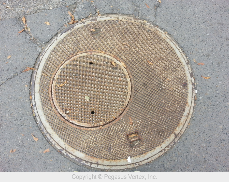
Finding a good picture of an eccentric annulus was challenging until Dennis (Global Sales Manager of PVI) and I walked down a street in downtown Calgary yesterday. I took a picture of this interesting sewerage cover. Dennis immediately guessed what I wanted to do with it, “Picture for your blog article about eccentricity?”

Eccentric Annulus

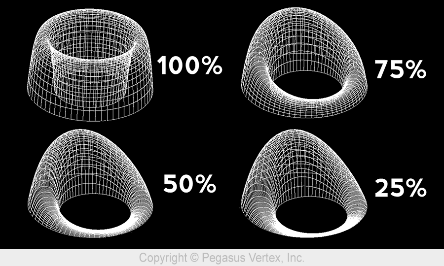
Picture 1: Eccentric Annulus

Many drilling engineering textbooks and modeling software assume concentric annulus because it is easy to model the fluid dynamics in it. Unfortunately, the most natural state of pipe in a well is almost always close to one side of the wellbore, if not touching, especially in a deviated well. Casing centralizers keep casing from contacting the wellbore wall. Even with centralizers installed, the casing between centralizers will still deform (sag) and could contact the wellbore.

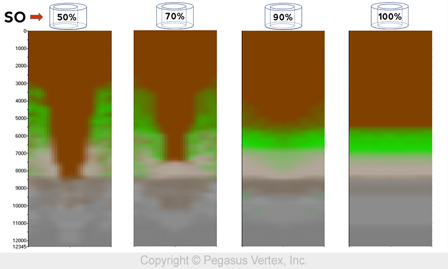
An eccentric annulus has the same cross-section area as the concentric annulus. However, the flow through the eccentric annulus exhibits various forms. The following picture shows the velocity profiles in annuli with various degrees of eccentricity. The percentage represents casing standoff. A standoff of 100% means a perfectly centered pipe while a standoff of 0% represents the situation that the casing is in contact with the wellbore.

Velocity Profiles

Picture 2: Velocity Profiles

The eccentric annulus has many unique characteristics such as less frictional pressure drop than that in concentric annulus. As the standoff gets lower, less energy is required to move the fluid, and mud removal becomes a problem in the narrow side.

To easily view the numerically simulated results of the fluid mixture in the annulus, we are going to unwrap the annulus into a 2D picture. In this picture, the middle represents the narrow side and the 2 edges represent the wide side.

Picture 3 shows the mud concentration with various standoffs.

Mud Concentration for Various Standoff

Picture 3: Mud Concentration for Various Standoff

A well-centered pipe in a wellbore will lead to a more uniform axial velocity profile and shorter fluid interface length. As standoff approaches 0, the narrow side flow could even be blocked, leaving fluid not displaced.

Casing Centralizer Series – 3: Modeling

We are going to study on the 5 parameters affecting casing standoff.

1. Well trajectory

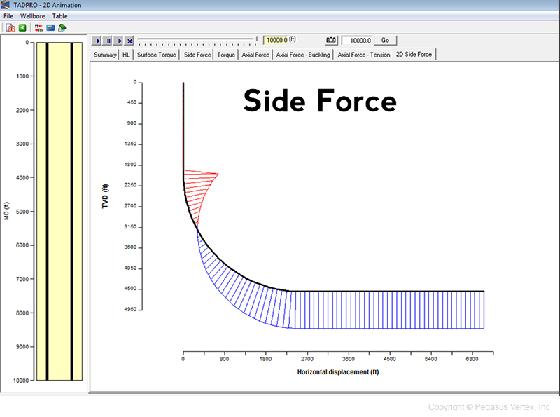
Well trajectory is expressed in terms of survey data, consisting measured depth, inclination and azimuth angles. It defines the shape of the well path and thus has great impact on the direction and magnitude of the side forces that pull the casing string to the wellbore. Fig. 5 shows the magnitude and direction of the side force distribution on a casing in a horizontal well.

Fig. 1. Side Force Profile

Fig. 1. Side Force Profile

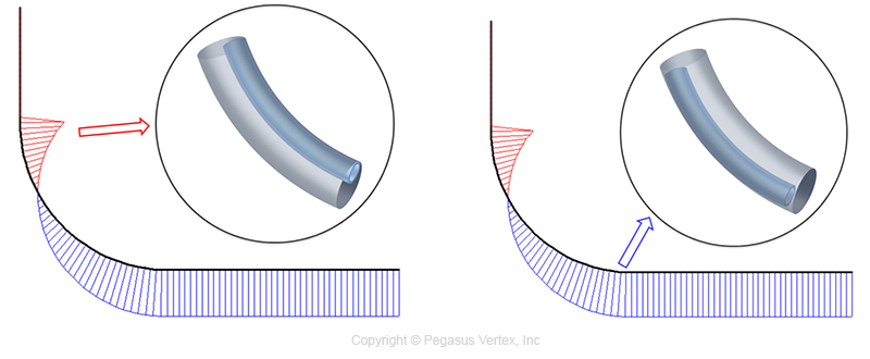
For a casing section in a build-up or horizontal section of wellbore, the weight of pipe pulls the casing toward to the lower side of hole. The blue lines indicate that the casing touches the lower side of wellbore. The upper section of the casing string has to sustain the weight of lower casing sections. This creates tension force along the casing string.  Wellbore doglegs cause the resultant force to pull the casing toward the upper side of the hole, as indicated by the red lines. Therefore, casing string in a deviated or horizontal well always touches the wellbore, upper or lower side.

Fig. 2. Side Forces with Casing Positions

Fig. 2. Side Forces with Casing Positions

Generally speaking, horizontal or extended reach wells require more support from centralizers to maintain a good standoff profile.

2. Casing size and weight

Casing weight determines the gravitational force which pulls the pipe toward the lower side of the borehole. The heavier the casing string is, more or stronger centralizers are required.

3. Fluids inside casing and in annulus

The buoyancy force calculation is further complicated by the multi-fluid configuration during a cementing job. When heavy cement slurries are inside the casing and light drilling mud in the annulus, the effective weight of casing is at its greatest. On the other hand, when cement slurries are in place and displacement fluid inside the casing, the buoyancy is at its peak and the effective weight of the pipe is the least.

When we design the centralizer placement for the scenario of cement slurries in place, it favors us to have less effective casing weight, pulling the casing string downward; but when the cement slurries are inside the casing during the displacement, the lower standoff could cause mud channeling problems. It is better to study standoff for all the situations.

4. Centralizer properties

Not all centralizers are created equal.  Centralizer manufacturers are striving to improve the performances of their products.

For solid centralizers including mold-on type, the blade OD is the key parameter as far as the casing centralization is concerned.

For bow-spring centralizers, the restoring force is the measurement of the strength of a centralizer. It is defined as the side force to deflect the bow by 1/3 or its original height.

5. Centralizer placement

Once the well is planned, casing designed, cementing procedure prepared and centralizer type selected, we do not have many options other than placing the centralizers strategically to achieve the desired standoff. However, this is also a great leverage.

Poor spacing will result in poor standoff even with the best centralizers in the market.

Casing Centralizer Series – 2: Standoff

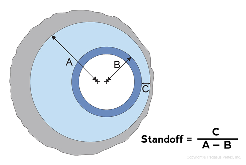
The term standoff (SO) describes the extent to which the pipe is centered (Fig. 1).

Fig. 1. Definition of standoff

Fig. 1. Definition of standoff

If a casing is perfectly centered, the standoff is 100%. A standoff of 0% means that the pipe touches the wellbore.  Regardless of the centralizer type, the goal is to provide a positive standoff, preferably above 67%, throughout the casing string.

The casing deflection between centralizers obeys the laws of physics. An engineering analysis can help both operators and service companies arrive at the optimized number and placement of centralizers for a particular well.

The casing standoff depends on the following factors:

  • Well path and hole size
  • Casing OD and weight
  • Centralizer properties
  • Position and densities of mud and cement slurries (buoyance)

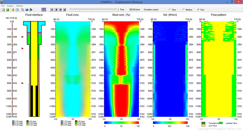
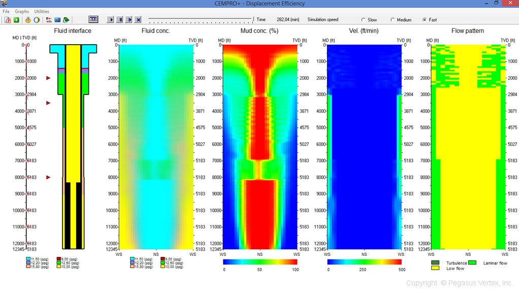
Incomplete mud removal causes poor cement seal and non-productive time.  A good casing standoff helps reduce the mud channeling and improves the displacement efficiency. The following 2 pictures illustrate the impact of casing standoff on displacement efficiency.  The 3rd track in Figure 3 shows the mud concentration in the annulus after a cementing job with 0% casing standoff.

Fig. 2. Displacement Efficiency for Casing Standoff of 0%

Fig. 2. Displacement Efficiency for Casing Standoff of 0%

You can see that there are some large red areas, which represent the high percentage of the remaining mud, in the narrow side (NS) of an eccentric annulus.

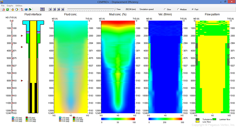
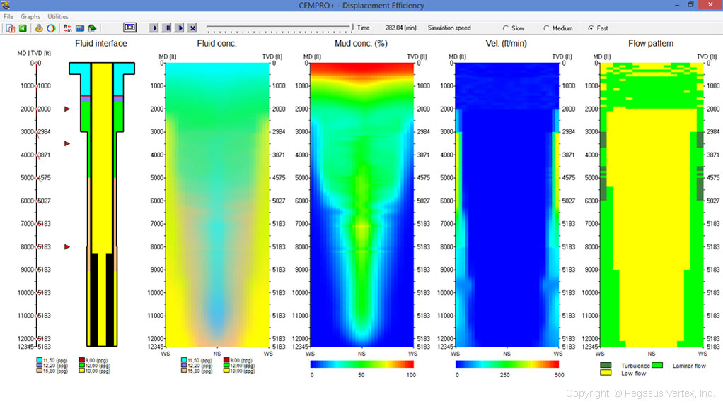
We kept everything else the same and only changed the casing standoff to 70%.  Now the displacement efficiency improved significantly, as shown in the following picture.

Fig. 3. Displacement Efficiency for Casing Standoff of 70%

Fig. 3. Displacement Efficiency for Casing Standoff of 70%

Like The Barriers on The Road

This is a story about a town located at the bottom of a deep valley.

The Vally

The only road into town was steep and windy, barely hanging on to the steep mountain-side surrounding the town. Very often, cars traveling into town would get too close to the edge of the road and tumble into the valley. Over time, the town spent hundreds of thousands of dollars responding to wrecks and they got tired of going out to respond to the same thing over and over. The town’s people rendezvoused to discuss the matter and how to solve it. Some folks thought they should ignore what was happening and let people fend for themselves. Others thought they should continue to help the people who went off the road, but should charge them for the costs involved. A few suggested that they should just close the road so those strangers wouldn't cause them any more problems. The majority of the people quickly acknowledged that the road posed a risk for strangers but also for friends, family and the townspeople themselves. Since nobody agreed to a specific solution, one person suggested they put up a barrier on the edge where cars most often went off the road and everybody agreed and so they did. Over the years, the barrier cost the community far less than all the rescuing they had been doing for so many years. A simple barrier was the solution.

It's a simple story, but a great metaphor for prevention. Like the barriers on the road, for more than 6 decades, casing centralization has been established as being essential to efficient mud removal and therefore to a successful cementing job. Prior to a production it is very common for field engineers to spend time improving casing centralization using software, particularly for highly deviated wells. However today, while long lateral wells are being drilled, they become more challenging in getting the casing to bottom and achieving good zonal isolation. That is why casing centralizers play a key role in achieving these objectives and should be evaluated differently than they have been in the past.

Predicting casing standoff is essential since not knowing where to locate the centralizers and how many are needed can cause several problems. The main reason for centralization is to ensure a uniform distribution of cement around the casing. No centralization or poor centralization will cause channeling of the cement and therefore produce poor cement adherence.

What do centralizers prevent?

  • When running a casing, the adequate use of centralizers reduces the chance of wall sticking.
  • In deviated wells because of the increased amount of support, the casing requires to stay in the center of the hole – especially in build-up sections - a more dense distribution of centralizers is required than in straight holes.

There are two main types of centralizer:

  1. Spring (Bow) Centralizers
  2. Rigid Centralizers

Spring (bow) centralizers are often used for vertical and deviated wellbores and rigid centralizers are used for horizontal wellbores. The method of installation for both of these depends entirely upon the centralizer design. However, care must be taken to ensure the quality of the cementing job. Centralizer placement is synonym of prevention.

For this PVI developed CentraDesign software that optimizes the centralizer placement, predicts casing standoff and torque and drag for extended reach drilling and deviated wellbores.

CentraDesign (Centralizer Placement)

CentraDesign also determines the number and placement of centralizers, hence providing both service companies and operators with a very sophisticated yet easy to use tool that will help prevent problems during the cementing process.

Prevention is like the barrier put up to keep cars from going over the edge and it works to keep unwanted things from happening in the first place.

The Risk of Not Keeping Risks Under Control

American writer and best-selling author Denis Waitley said:

“Life is inherently risky. There is only one big risk you should avoid at all costs, and that is the risk of doing nothing.”

Risks are everywhere. I was watching a documentary on earthquakes and hurricanes and it got me thinking about how there are risks in everything that surrounds us, but that doesn’t stop us from improving and moving forward. We have to acknowledge that risks exist. Taking risks is in our human nature and when something goes wrong we work towards being more prepared in the future.
Some people are reluctant to take risks because they’re somewhat afraid, but the reality is that taking risks can:

  • Open people up to new challenges and opportunities.
  • Empower people to establish new limits in their minds.
  • Stimulate people to become more creative.
  • Result in positive outcomes.
  • Help people to clearly define what they’re trying to achieve.
  • And once they have become accustomed to taking risks, they break free from the average way of thinking.

In the drilling industry every step and every decision has to be made, yet it is necessary to drill for oil. As a nation on the wheel, the usage of petroleum has become an everyday thing not only for the United States but for the rest of the world as well. So basically it’s all about risk control for every aspect of life including the drilling industry, and in this case it is all about a well done cementing job.

For drilling engineers, cementing seems to be more of an art than a science or technique. Cementing is the process of displacing cement to the annular space between the well-bore and casing or to the annular space between two successive casing strings. With the latest technologies and analytical software such as CentraDesign and CEMPRO developed by PVI, cementing engineers can use these types of software to ensure a complete and proper cement displacement.

A successful cementing job is one of the most important factors in the productive life of any well. However, challenges are always coming along as the wellbore goes deeper and to the places that are harder to reach. It’s already prevalent to predict a cementing job by computing the downhole temperature and pressure. If the cementing job is well done, all the risks are under control; a longer life of the wellbore and a higher productivity is promised.
We are living in a world where technology is advancing quickly. As PVI developers we are trying our best to develop more advanced software to meet the new needs. That’s why we developed CEMPRO+, the ultimate enhanced version of PVI’s mud displacement model, CEMPRO®.

CEMPRO+ - CEMPRO with displacement efficiency

Designed for land, offshore, conventional and/or foamed operations, CEMPRO+ uses advanced numerical methods to solve momentum and continuity equations on 3D grids and calculates the fluid concentration as well as the displacement efficiency. It accounts for many factors that can affect the efficiency of displacement jobs, including fluid properties, pumping rates, casing standoff and complex wellbore geometry.

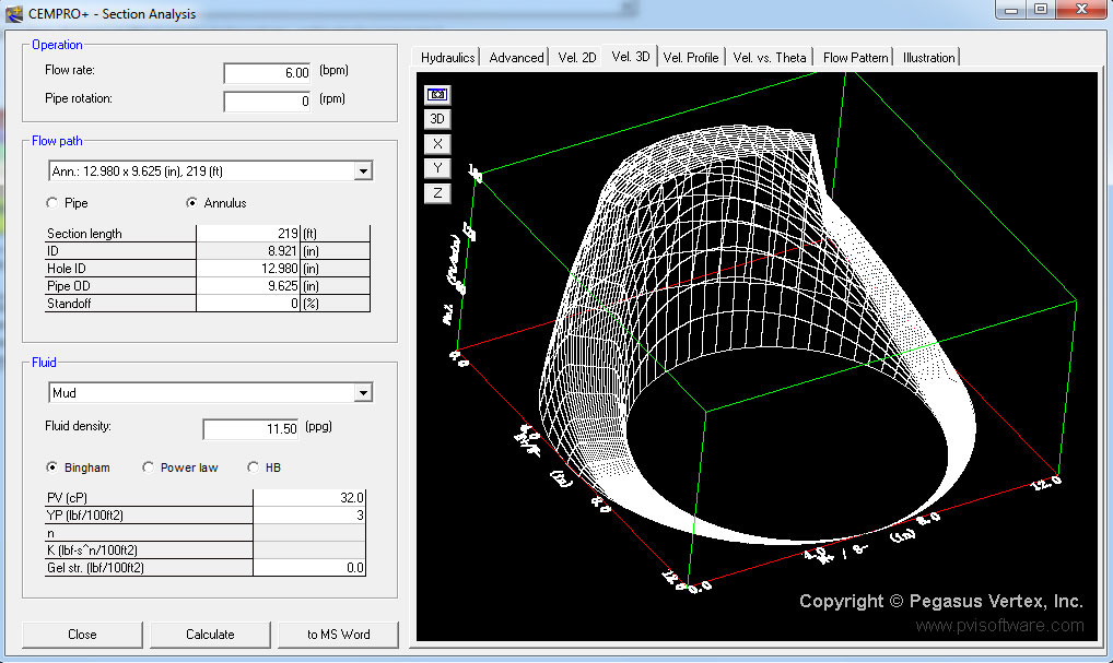
3D Plot of Velocity Profile - CEMPRO+

Although taking risks requires some blind trust in most cases, with a well done cementing job, drilling does not need to be a problem, but the complete opposite. We’ll never know what we can accomplish until we take the risks, and we can always get the best rewards by finding the right solutions or tools to keep the risks under control.

Prevention is Better than Cure

Many of us wouldn’t go to see a doctor until we get sick. This not only costs more money, but also causes more pain. Preventive medical assessments may be seemingly unnecessary and unpleasant, but it can help identify potential health problems, save lives, and reduce medical costs.

We often hear of some famous physical doctors or medical experts, who have remedied illness, when troubles surfaced. As a matter of fact, we are all doctors ourselves, in a sense that we take care of our daily lives, command our bodies to certain tasks, and avoid certain activities. We, as doctors ourselves, play a big role every day in maintaining our health. We are all CEOs of our own way of life and happiness. If we do our best to keep up good habits, take care of our bodies regularly, we will save ourselves lots of trouble and money in medical expenses.

Prevention can be beneficial to drilling engineering as well. Our experiences gained and lessons learned help us make right decisions for our next well. Drilling engineering software also serves as a great tool to identify any potential problems in our existing drilling plan or make sound engineering designs.

Take an example of cementing job design. One of the key elements of a successful cementing job is good displacement efficiency (less mud channeling). We have known that several parameters such as casing standoff, flow rate, differentials of fluid properties and hole deviation affect the effectiveness of fluid displacement. Now, with the help of computer modeling, we can see the impacts of these parameters. The following picture shows the mud concentration in the annulus at the end of the cementing job, where casing standoff is 0% throughout the wellbore (casting touches the borehole).

Displacement Efficiency for Casing Standoff 0% - Pegasus Vertex, Inc.

Displacement Efficiency for Casing Standoff 0%

You can see that there are quite large red areas in track 3, indicating poor displacement efficiency.

Now, we change the casing standoff to 70% and keep the other parameters the same. The following picture shows the much improved mud concentration after displacement:

Displacement Efficiency for Casing Standoff 70% - Pegasus Vertex, Inc.

Displacement Efficiency for Casing Standoff 70%

Time and money (not to mention headaches) could be saved if drilling engineers undergo through all the engineering assessments before problems arise. Be sure to use your know-how, skills, experiences, lessons and available drilling software. Having a complete understanding of what will happen gives you a greater sense of control, reduces risks and saves money.