
FAQ - Frequently Asked Questions
Click the most frequently asked questions to view the solutions.
PVI’s Transition to LINQX
- 1. Will there be any changes to PVI’s business operations?
- 2. Have PVI’s banking details changed?
- 3. Has PVI’s office address changed?
- 4. Can I still reach PVI through the same contact details?
- 5. Will PVI’s social media channels change?
- 6. Where should I send check payments?
No, our operations will continue as usual with the same high level of service and commitment you’ve come to expect. The acquisition enhances our capabilities while maintaining uninterrupted support for our customers.
Our bank details remain unchanged. Please continue using the existing information. We’ll notify you of any updates in advance.
Our office location remains the same at 6100 Corporate Dr., Houston, TX 77036. We’ll notify you of any changes in advance.
Yes, our phone numbers and email addresses remain unchanged. You can continue to reach out to us through your usual points of contact.
For now, our social media channels remain the same. You can continue to follow us for updates and industry insights. Later this year, we plan to merge our channels under LINQX to provide a more unified experience—stay tuned for more details.
Please send all check payments to our new mailing address:
Pegasus Vertex, LLC – A LINQX Company
5050 Westway Park Boulevard, Suite 150
Houston, Texas 77041
Should there be any future updates, we will inform you in advance. If you have any further questions, feel free to contact us. We appreciate your continued trust and partnership!
General Information/Products and Services Inquiry
- 1. What is PVI's software leasing model?
- 2. What is U&M plan?
- 3. How can I keep my software up-to-date?
- 4. How is PVI software supported?
PVI discontinued selling perpetual licenses for its products as of January 2023. Instead, PVI licenses its software in various terms, i.e. one month, three months, six months, or a year. Contact sales@pvisoftware.com for more information about licensing.
The Technical Support, Upgrade and Maintenance Plan (U&M) is a plan that covers three categories: Technical support, Upgrade and Maintenance.
- Technical support services include telephone, e-mail and web-based support from 9:00 am – 6:00 pm USA Central Time. PVI provides technical explanations on software, direct support from PVI (no 3rd party "level-tier" support) and rapid response time (no automated phone system, phone tag or minimum wait period). We respond within 24 business hours.
- Upgrade services include software upgrades and updates at no additional cost.
- Maintenance services is where we provide necessary support to ensure PVI software works with updated Windows operating systems.
PVI U&M will be valid for those with a leasing license for as long as the license is valid. Users with perpetual licenses will have to renew their U&M once it expires in order to retain its service; U&M is independent of license length for perpetual licenses.
The PVI development team constantly strives to enhance all aspects of current software in order to stay in the forefront of advanced drilling technologies. Due to these efforts, our software does have updates from time to time. To update your software, please contact: sales@pvisoftware.com. Current U&M customers can update at any time for no additional fee.
PVI software is supported in many different ways. A detailed user's manual is included with every software package. You can also find a digital version of the user's manual in our software by clicking the help button located at the upper right hand corner of the software interface. You can e-mail us at support@pvisoftware.com with any technical issues and a support representative will return your e-mail promptly. For current U&M customers, PVI provides technical support from our IT staff, developers and sales team by phone, e-mail or web-based support. Contact sales@pvisoftware.com for more information.
Installation/Troubleshooting
- 1. How to install PVI software?
- 2. How to run PVI software?
- 3. Do I have to use administrator privileges to use PVI software?
- 4. How do I update my current PVI software to the latest version?
- 5. How do I determine my software version?
- 6. How to solve "Run-time error '339': Component 'TABCTL32.OCX' or one of its dependencies not correctly registered: a file is missing or invalid" problem?
- 7. What should I do if the software in the client's computer cannot find the server HASP dongle?
- 8. If I get an error message showing “an error occurred while downloading the file http://saturn.installshield.com/is/prerequisites/microsoft.net framework 4.0 full.preq. What would you like to do?” during installing, how do I fix it?
- 9. How to solve "The Microsoft® jet database engine cannot open the file ".mdb", it is already opened exclusively by another user, or you need permission to view the data." problem?
- 10. How do I solve the problem of "draw2d.ocx" "wbocx.ocx", "tabctl32.ocx", or some other ".ocx" file that is not correctly registered?
- 11. How to solve the "ODBC driver not found" problem?
- 12. What does "Feature not found", "USB dongle (key) not found", and "Not authorized to run this problem" mean?
- 13. I plugged in the dongle, but the software tells me to activate license or that my license was expired. What should I do?
- 14. When upgrading Windows® 8 to 8.1, the system asks to uninstall Sentinel Runtime Drivers. What should I do?
- 15. I received the error message "you don't have an appropriate license to use this functionality". How do I solve this problem?
- 16. How to solve "There is no seat available" problem?
- 17. How to setup network license?
- 18. How to activate the standalone license?
- 19. How to restart the license manager service?
- 20. How to restart the sentinel LDK license manager service?
- 21. What to do when you received a message from Microsoft Edge stating that the file "was blocked because this type of file can harm your device"?
Before installing the software, please log in with administrator privileges. You may get the setup instructions from the software CD or download the link sent to you by the PVI support team.
- CD Installation: Insert the CD into the CD-ROM drive. The installation program will automatically start. Simply follow the on-screen instructions to complete the installation.
- Download Link Installation: Click the download link to download the .exe file. Double click to install the software.
After installing the PVI software, the software icon will appear on your desktop, double click it to run the software.
No, but the installation requires administrator's privileges. As long as the user has the privilege to modify the Windows® folder you will be fine. You can grant normal users (i.e., not the administrator) the privilege to read and write the Windows® folder as well.
You can just download the latest software and re-install. Re-installing will automatically carry over the data you have with your old version.
To determine your software version, open the program and select Help > About. Release histories for the software can be viewed/discussed with the relevant PVI technical sales rep if desired.
This alert message happens when the tab control is not correctly registered. You can choose to manually register this ".ocx" file.
- Launch the command prompt, then route to "C:\windows\system32", type in "regsvr32 tabctl32.ocx" and press enter. A window will pop up and tell you that it is successfully registered.
- Alerts concerning ".ocx" and ".dll" file registrations can be solved in the same way above, by just changing the file name.
You can try to configure the "nethasp.ini" file in the installation directory. You can specify the server's IP address at "NH_SERVER_ADDR". This will save time when searching for the hasp dongle in the intranet.
This error indicates downloading MS.net frame fails, make sure your Internet connection works well and then install the software again.
This alert message pops up when you do not have MS Access installed on your computer. Install the MS Access and restart PVI software. If you do not have the access, contact our support team: support@pvisoftware.com for more solutions.
This issue occurs during the following circumstances:
- You do not have administrator privileges when you run PVI software. The software needs to register the supporting file in the Windows® system folder. Normally, only the administrator has privileges to modify the files in the system folder (including registration).
- The ".ocx" file is not correctly registered in your system configuration. You can run command prompt with administrator's privilege, reroute to the Windows® system folder and type in "regsvr32 draw2d.ocx" (or other .ocx).
The database used in PVI software is created using Microsoft Access®. You do not need to have Access installed on your computer to run the software, but you need the ODBC driver of Access to communicate with the database. To solve this problem, install Microsoft Access® on your computer (the ODBC driver for Access will be installed automatically) or you can manually install the ODBC driver for Access.
These messages may indicate that your license is expired. Please e-mail us at support@pvisoftware.com and let us know which software you are using, the version and alphabet letter on the dongle, so we can better assist you in updating your license.
It may take a while for a new USB port to install the driver and read the dongle. Wait until the dongle has a solid red light before you start the software, if problem persist try another USB port.
When you upgrade your operating system from Windows 8® to Windows 8.1®, the system may ask you to uninstall "Sentinel Runtime Drivers".
To proceed:
- Open control Panel, find the 'Add Remove Programs', and uninstall "Sentinel System Driver/Sentinel Runtime" entirely.
- After upgrading your operating system from Windows 8® to Windows 8.1®, install the newer HASP on your computer. Click here to download the HASP package. If the problem still exists, reinstalling PVI product may be required.
Please make sure an IT expert is with you if you want to reinstall it by yourself. You can also contact our Technical Support for help.
Make sure you have admin privilege. Go to C:\Program Files\PVI\[your PRODUCTNAME]\GSfix290.exe, double click to run this .exe file under Administrator privilege. Restart your PVI software. If problem still exists, please contact support@pvisoftware.com for further help.
This is a network license alert where the user limitation was triggered. Contact us or e-mail support@pvisoftware.com directly to add more seats.
For customers who have purchased the network license, please refer to below .pdf file for detailed instructions.
Network License Installation Instructions
For customers who have purchased the standalone license, please refer to below .pdf file for detailed instructions.
Registration Procedure
Please refer to the .pdf file below for detailed instructions.
License Manager Service Restart Instructions
Please refer to the .pdf file below for detailed instructions.
Sentinel LDK License Manager Service Restart Instructions
Please refer to the .pdf file below for detailed instructions.
Microsoft Edge File Downloading Instructions
Software
CEMLab - Cement Lab Data Management
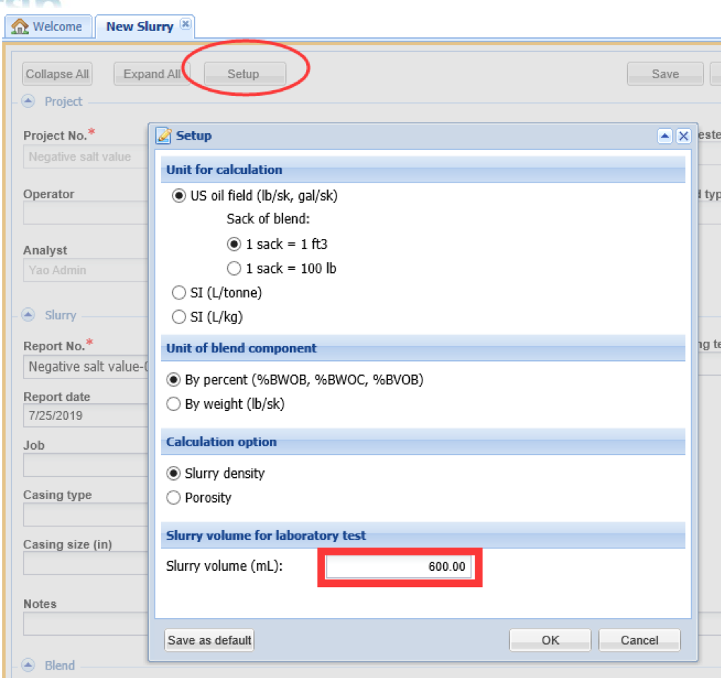
- 1. How to change the slurry volume for CEMLab calculation?
The slurry volume can be customized for each slurry.
You can open the Setup window by click on the Setup button on the top of any slurry page, and change the slurry volume, say 600 mL. Then please click on the “Save as default” button at the left bottom corner to let CEMLab remember your settings. After that once you create a new slurry, its volume will be 600 mL.
CEMPRO+ - Cementing Job Model
- 1. How does the input of mesh size and calculation points in “Displacement Efficiency” tab impact the predicted mud removal results?
- 2. Can CEMPRO+ do plug jobs?
- 3. How does CEMPRO+ calculate foam rheology and its frictional pressure loss? (Lucas, Altcem)
- 4. What does Friction Factor Adjustment in “Others” tab below “Fluid” tab mean? What calculation will it affect?
- 5. How are "fluid compressibility" and "P/T dependent density and rheology" in CEMPRO+ related to each other?
- 6. We need more rows for open hole sections. Why does it only allow 45 rows?
CEMPRO+ uses mesh-based numerical methods to solve flow and transports equations to predict the displacement efficiency. The mesh points and size are definition of mesh resolution. Users can specify the mesh resolution in each of depth, radial and azimuthal directions according to the accuracy requirement. Using a high-resolution mesh (increasing number of mesh points or decreasing mesh size) can increase the accuracy of the result, yet also significantly increase the calculation time.
CEMPRO+ is designed for casing/liner cementing. It can be used to simulate mud displacement with drill pipe in the wellbore, track the spacer, mud and slurry fronts and to see if the volumes are good for your job. However, when doing plug job, you’ll want to calculate for the final condition after you remove the drilling pipe – this process is not accounted in CEMPRO+. You can hand calculate the pipe volumetric displacement to estimate the fluid fronts, but not the slurry contamination after the drill pipe is removed.
To calculate the rheological property of foam, first calculate the N2 fraction(f) in the foam. Pressure and temperature are involved to calculate the N2 fraction, its time, and depth dependent due to gas compressibility. One dimensional spacial mesh along the wellbore is introduced in CEMPRO+ to calculate the gas fraction and other foam properties from point to point.
Friction Factor (FF) Adjustment means the friction factor change because of the fluid change in the annulus. We input FF in the “Open Hole” tab for each casing, assuming drilling mud is between casing and wellbore. When we pump various fluids into the wellbore, and as they enter into the annulus, they may affect the FF. Friction Factor (FF) Adjustment input allows the user to reflect the change. These values are used to calculate torque and drag for liner cementing job. Unless you have some real data, it is difficult to know the exact FF Change %, but generally speaking, cement slurry may cause the increase of FF.
Fluid compressibility is a tool for estimating pressure caused volume change, the results are not included in the report. The pressure is the final hydrostatic pressure only at the end of a job. P/T dependent density/rheology is a different and a more advanced functionality.
Once checked on, it’s considered in the whole simulation. Because the temperature is depth and time dependent, fluid volumes, fronts, ECDs and others are all affected and different from the case if you ignore P/T dependency. The difference will also be reflected in the report.
To check the difference, you can use a case with P/T checked on (e.g., sample case 15, 16) and run the same case with P/T checked off and compare the two.
CEMPRO+ limits the number of rows in order to speed up the computation. With the built-in algorithms, handling thousands of open hole sections in the program is currently not practical, due to limit of memory and CPU time. Averaging the intervals to reduce the number does not cause any error in the volume calculation. For pressure calculation the reduction of accuracy should be minimum as well.
CentraDesign - Centralizer Placement Software
- 1. Can the program handle multiple types of centralizers on the same string?
- 2. How is torque and drag affected when centralizers are free to rotate?
- 3. What is the impact on standoff when selecting casing coupling at centralizer vs. at mid span?
Yes. To accomplish this, copy and paste the casing component to break it up into several lengths in the pipe table. Different types of centralizers can be added to each section.
- Friction factor defined in Wellbore Interval table is the friction factor between wellbore internal wall and pipe body.
- When pipe with centralizer, program assumes that there are enough centralizers to support the pipe and the pipe will not contact with the wellbore wall. If friction factor between wellbore wall and centralizer is less than that between wellbore wall and pipe body, FF reduction in Pipe table is positive, otherwise it is negative or zero. The number of centralizers will affect the torque and drag by two ways. One is to add the weight of centralizer to the adjusted weight of pipe. The other is to adjust the FF reduction if the pipe body still contacts with the wellbore wall.
- The FF value in axial direction and in circumferential direction is depending on the ROP/Tripping speed and RPM. If no rotate, all the FF will be in axial direction; if no movement in axial direction, all the FF will be in axial direction.
- The Tool/Centralizer is free to rotate: The rotational FF is used to calculate torque. CWPRO assumes that the rotation (RPM) is between pipe and Tool/Centralizer and there is no rotation between wellbore wall and Tool/Centralizer. Therefore, when calculating the axial drag, all the FF is in axial direction
- The program calculates the standoff from centralizer by assuming that there is no coupling. Standoff 1: standoff at centralizer; Standoff 2: standoff at mid-span
- The program calculates the standoff from coupling by assuming that there is no centralizer. Standoff 3: standoff at coupling
Casing coupling at mid span: If standoff 3 is greater than standoff 2, standoff 2 will be adjusted to standoff 3.
CleanMax+ - Advanced Wellbore Cleanup Software
- 1. What are the differences between DISPLEX and CleanMax+?
- 2. What are the distinctive features of CleanMax+ for deep water operations?
- 3. Can I specify my own clean-up tools and create the tools schematic by uploading my own tool pictures?
- 4. In “Input Setting – Calculation”, there are two options under “Pressure Calculation”. What is the difference between “API” and “Dodge and Metzner” methods?
- 5. Why is there an option for a dependency?
CleanMax+ covers all functions of DISPLEX and is equipped with more advanced features like the following:
- Up to 16 operation stages for land wells
- Combination of 9 flow paths for deep water operations
- Fluid compressibility
- Pressure and temperature dependent rheology
- Circulation sub and gravel pack
- Coiled tubing operation
CleanMax+ is designed for deep water operations involving displacements using the choke, kill, and boost lines. CleanMax+ predicts the temperature distributions in the wellbore by calculating the transient heat transfer between wellbore and sea water/rock formation. It can simulate temperature and pressure dependent density and rheology properties of fluids, commonly associated with HTHP environments.
Yes. User can define the clean-up tools configuration in “Pipe” section, and import their own tools pictures. The WMF (commonly generated by AutoCAD) format picture is required to plot the tools schematic.
The difference of the 2 options is on the critical Reynolds number for power law fluid.
API method uses charts to determine critical Reynolds number while Dodge and Metzner method uses a series of equations including the following ones:
- Laminar:
NRec = 3470 - 1370n - Turbulent:
NRec = 4270 - 1370n
These two types of fluids have their own coefficients to adjust Fann Reading data when considering pressure and temperature effects.
CWPRO - Casing Wear Prediction Software
- 1. Can the software calculate collapse strength of worn casings?
- 2. How do I select an appropriate wear factor?
- 3. How does CWPRO deal with cumulative casing wear caused by different drill string operations?
- 4. When to apply non-liner correction to wear calculation?
Yes. For worn casings, a factor of the worn casing collapse strength to the new casing collapse strength will be calculated first. Then this factor will be used to obtain the collapse strength of the worn casing.
Wear factor is affected by mud type, mud additive, whether lubricants are applied, casing interior, tool joint protector material if protectors are placed…CWPRO provides suggested wear factor based on the joint-industry project, DEA-42.
User can also get the wear factor from the manufacturer if any wear factor reduction tool is placed.
CWPRO is intelligent enough to handle complicated casing structures and abundant operations inside the casing. During each operation, the software would define the exposed area between a casing and a drill string to calculate the exact wear. Casing condition after one operation would be the initial condition for the next operation. Casing wear accumulates in the sequence of operations.
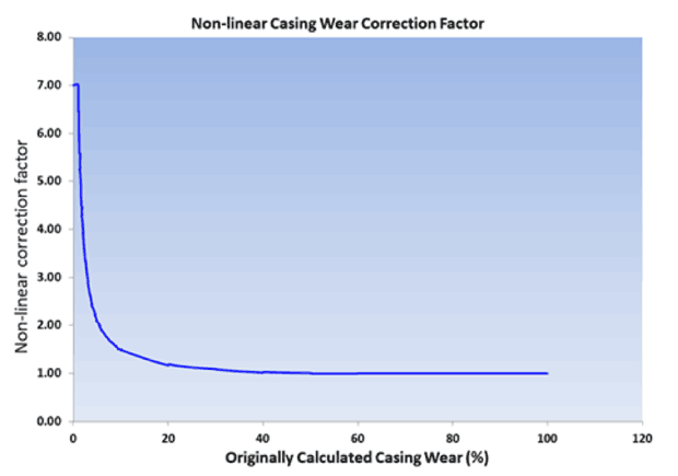
The default casing wear calculation uses linear wear factor, meaning that casing wear increase linearly with time. But experiments have shown that the wear factor decreases with increasing wear depth and wear time. As casing wear increases, casing wear speed decreases and eventually stables when wear exceeds about 50%.
If the casing wear result is small (less 5%), it is suggested to apply the non-liner correction. The illustration of this non-linear correction factor is shown below.
HYDPRO - Drilling Hydraulics Software
- 1. When I perform a hydraulics run, the hole cleaning graphs do not populate. How do I get hole cleaning graphs in the outputs?
- 2. What do the “RPM effect on hydraulics”, “Eccentricity effect on hydraulics” and “Tool joint effect on hydraulics” options do?
- 3. What causes HYDPRO calculation time to increase?
- 4. What is the difference between ECD and EMW in Report table in Output Window?
- 5. Is input setup for calculation matching different in HYDPRO and MUDPRO+?
- 6. How does survey data differ in HYDPRO and MUDPRO+?
- 7. How do the advance options (ROP, RPM, Eccentricity, Tool Joint Consideration) effect HYDPRO/MUDPRO+?
- 8. Do I need to turn off Backpressure in HYDPRO for calculation matching to MUDPRO+?
To calculate the hole cleaning, select the Advanced (Three-layer) model in the Calculation Setup window. The ROP in the Hydraulics tab must also be greater than 0.
These options affect the hydraulics calculations by accounting for the flow of fluid through restrictions, around and across the tool joint, and in an eccentric annular space. These calculations are complicated, and become even more so with rotation. All the calculations are based on empirical formulas. Any discrepancies, if any, between prediction and field data can give useful insights into the effect of RPM, Eccentricity and tool joint.
The hydraulics sensitivity analysis can dramatically increase the calculation time, especially when all of the sensitivities are selected.
Surge/swab calculations
The three-layer model uses the iteration method to find the cuttings bed height. It takes the longer to calculate than the API method.
To improve the speed,
- Don’t run the hydraulic sensitivity every time.
- Change the calculation interval to a larger value. The calculation interval defines the bit depth locations at which the pressure profile calculation is conducted. Such as If the calculation interval is set to 500 ft, the program will calculate the hydraulics profile when the bit moves every 500 ft.
EMW: Equivalent mud weight. It includes the cuttings contribution.
EMW = cuttings density * cuttings concentration + mud weight * (1 – cuttings concentration)
ECD: Equivalent circulation density. It includes the annulus frictional pressure loss.
ECD = EMW + annulus frictional pressure loss/0.052/TVD.
The mathematical model in HYDPRO and MUDPRO+ are the same. If the inputs are equal, the results should be as well. Differences in the survey/wellpath and small rounding differences in the background of the calculations are likely to occur.
We recommend the calculations between HYDPRO and MUDPRO+ with ECD and PP differences of ≤ 3 % or less than ± 0.3 ppg be considered a match.
Please refer to the .pdf file below for detailed explanation.
HYDPRO and MUDPRO+ Hydraulics Matching Explanation
HYDPRO allows user to input detailed survey data, while MUDPRO+ uses the MD and TVD from all of the daily reports. It allows HYDPRO surveys to contain more depth entries and therefore often has a more accurate well path for the simulation.
Impact of the survey data tends to be small in PVI’s experience. If the MD and TVD values in MUDPRO+ match the survey data in HYDPRO, the results from both software will be close.
Please refer to the .pdf file below for detailed explanation.
HYDPRO and MUDPRO+ Hydraulics Matching Explanation
Please refer to the .pdf file below for explanation.
HYDPRO and MUDPRO+ Hydraulics Matching Explanation
MUDPRO+ does not consider backpressure, so it needs to be turned off in HYDPRO when comparing the ECD and pump pressure calculations.
Please refer to the .pdf file below for detailed explanation.
HYDPRO and MUDPRO+ Hydraulics Matching Explanation
MUDPRO+ - Advanced Drilling Mud Reporting Software
- 1. How to transfer wells?
- 2. How to fix a crashed database?
- 3. How to change the price of an item?
- 4. Is input setup for calculation matching different in HYDPRO and MUDPRO+?
- 5. How does survey data differ in HYDPRO and MUDPRO+?
- 6. How do the advance options (ROP, RPM, Eccentricity, Tool Joint Consideration) effect HYDPRO/MUDPRO+?
- 7. Do I need to turn off Backpressure in HYDPRO for calculation matching to MUDPRO+?
- 8. How do I export MUDPRO+ WITSML?
- 9. Is there a quick setup guide to help me transition to MUDPRO+ version 4.0 or later?
Please refer to the .pdf file below for detailed instructions.
Transfer MUDPRO+ Wells Instructions
Please refer to the .pdf file below for detailed instructions.
Crashed MUDPRO+ Database Troubleshooting
Please refer to the .pdf file below for detailed instructions.
Inventory Price Change Instructions
The mathematical model in HYDPRO and MUDPRO+ are the same. Generally speaking, if the inputs are equal, the results should be equal as well. However, the calculation interval/points and small rounding differences in the background of the calculation will likely occur.
PVI recommends calculations between HYDPRO and MUDPRO+ with ECD and PP differences of ± 3 % or less than + 0.3 ppg be considered a match.
Please refer to the .pdf file below for detailed explanation.
HYDPRO and MUDPRO+ Hydraulics Matching Explanation
HYDPRO allows user to input detailed survey data, while MUDPRO+ uses the MD and TVD from all of the daily reports. It allows HYDPRO surveys to contain more depth entries and therefore often has a more accurate well path for the simulation.
Impact of the survey data tends to be small in PVI’s experience. If the MD and TVD values in MUDPRO+ match the survey data in HYDPRO, the results from both software will be close.
Please refer to the .pdf file below for detailed explanation.
HYDPRO and MUDPRO+ Hydraulics Matching Explanation
Please refer to the .pdf file below for explanation.
HYDPRO and MUDPRO+ Hydraulics Matching Explanation
MUDPRO does not consider backpressure, so it needs to be turned off in HYDPRO when comparing the ECD and pump pressure calculations.
Please refer to the .pdf file below for detailed explanation.
HYDPRO and MUDPRO+ Hydraulics Matching Explanation
Please refer to the .pdf file below for detailed instructions.
MUDPRO/MUDPRO+ WITSML Exports
Yes, this guide is specifically designed to assist mud engineers transitioning from the older MUDPRO and MUDPRO+ software to the latest MUDPRO+ version 4.0.0 or later. It addresses the most common challenges encountered during the adoption of the new software. For more detailed inquiries or comprehensive usage questions, please consult your internal technical personnel or your company’s PVI sales representative.
TADPRO - Torque and Drag Software
- 1. How are friction factors (FFs) defined in TADPRO?
- 2. What is the calculation interval option?
- 3. What is the “Calculation on survey points” option?
- 4. What does the “Calculate torque and drag without FF reduction” option do?
- 5. What is the side force normalization length, and how does it affect side force?
FFs are defined in Wellbore Interval table. Cased hole friction factors (CHFFs) and open hole friction factors (OHFFs) are defined separately. These are user defined values, though recommended values are accessible using the quick help feature next to the FF portion of the table (the question mark button).
For sections of the string that have tools or centralizers, the friction factor might be reduced or changed. This can be accounted for at the bottom of the detailed table for each component by using a percent friction reduction.
If the tools/centralizers are free to rotate relative to the string, the rotational FF is used to calculate torque instead of the values listed in the wellbore intervals table.
It defines the locations of string bottom where the torque and drag profile is calculated. The smaller the calculation interval, the longer the calculation time.
The calculation interval simply determines how often points are calculated/placed in the history graphs. History graphs are hook load and surface torque, as well as stretch and twist graphs. The default interval is 100 ft, though smaller intervals can be chosen to increase the accuracy or smoothness of the history graphs. Since a full set of profile tables/graphs (side force/axial force/torque) are needed for each point placed in a history graph, choosing a small calculation interval can increase the required calculation time.
T&D software calculates in small segments and cumulatively sums the results, beginning at the bottom of the string and working up to the surface. Choosing the ‘calculate on survey points’ option will set the segment length to the distance between survey points, as reflected in the survey. Surveys with a 100 ft interval for a 15,000 ft well would result in 150 separate sections over which torsional and axial forces are determined.
For each string bottom location, in order to calculate torque and drag, the pipe is divided into many elements. Each component should have the same mud weight, wellbore size, pipe geometry and dogleg. Calculation on survey points ensures the same dogleg in each component.
This will run an automated comparison between the T&D model as set up and the T&D model without friction reduction applied. The without friction reduction T&D model affects the pipe tab only by setting the ‘FF reduction’ to zero and the tool/centralizer ‘free to rotate’ box to unchecked for all pipe components.
Side force is calculated as a force per distance (i.e. lb/ft). The normalization length simply multiplies the force per unit distance by a length. The normalization length does not affect the calculations, but rather the numbers displayed in the side force graph. At 100 lb/ft, a normalization length of 31 ft would show 3,100 lbs in the graph vs. a normalization length of 40 ft resulting in 4,000 lbs on that same graph.
When the side force is set to ‘per joint’, the normalization length will default to the joint length for each pipe component. It is therefore possible to have the side force normalized for different length components in the same graph, such as 31 ft for drill pipe and 40 ft for casing/liner.